Mục lục
- Tại sao nhiệt độ phôi chai quyết định mọi thứ ở phía sau
- Bản chất của ống phôi được ép phun
- Chuỗi nhiệt độ hoàn chỉnh: Bảy mắt xích, một kết quả
- Mắt xích 1: Nhiệt độ sấy nhựa và hàm lượng ẩm
- Mắt xích 2: Hồ sơ vùng trục vít, vòi phun và áp suất ngược
- Mắt xích 3: Cân bằng kênh dẫn nóng và độ đồng đều giữa các khoang
- Mắt xích 4: Nhiệt độ trục lõi, biến số chính thực sự
- Mắt xích 5: Nhiệt độ khoang ép phun và hình thành lớp bề mặt
- Mắt xích 6: Mất nhiệt trong quá trình chuyển giữa các trạm
- Mắt xích bảy: Nhiệt độ khuôn thổi và định hình cuối
- Dải nhiệt độ theo từng loại vật liệu
- Bản đồ khuyết tật: Mỗi lỗi nhiệt độ trông như thế nào
- Phần cứng kiểm soát nhiệt độ và thực hành đo lường
- Phương pháp chạy thử: Tìm và giữ cửa sổ quy trình
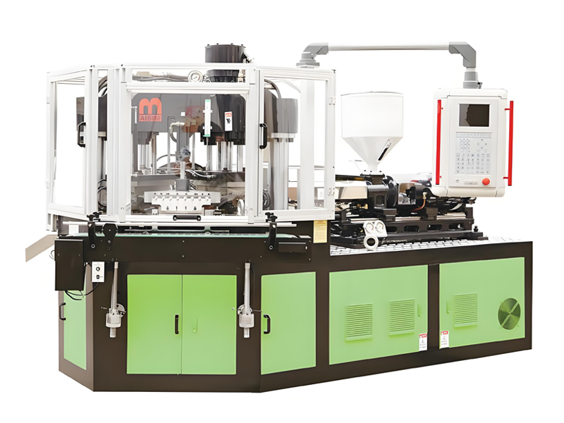
- Máy ép phun thổi chai Aibim
- Các ngành ứng dụng và sản phẩm cuối
- Hướng dẫn lựa chọn: Từ yêu cầu đến model
- Dịch vụ và hỗ trợ
- Câu hỏi thường gặp
- Kết luận
Tại sao nhiệt độ phôi chai quyết định mọi thứ ở phía sau
In one-step injection blow molding, parison temperature is not one process parameter among many — it is the variable that all other parameters are trying to compensate for. A parison that leaves the injection station two degrees too hot cannot be rescued by blow pressure, blow timing, or mold cooling; it will sag, thin out at the shoulder, and stick to the core rod. A parison two degrees too cold will resist inflation, whiten under strain, and leave a heavy base with a starved shoulder. Every experienced injection blow molding technician eventually reaches the same conclusion: when a bottle program will not stabilize, the answer is almost always somewhere in the temperature chain.
This guide is written for process engineers, technicians, and production managers who run or plan to run injection blow molding lines for small precision bottles. It maps the entire thermal chain of the one-step process, from resin drying through barrel zones, hot runner, core rod, injection cavity, station transfer, and finally the blow cavity. Each link is given working parameter ranges, the physical mechanism behind those ranges, and the defect signature that appears when the link drifts. The guide then provides material-specific temperature windows for eight resin families, a defect diagnosis map, hardware and measurement guidance, and a structured commissioning methodology.
Aibim, a Wanplas factory, has spent twelve years building three-station one-step injection blow molding machines and molds for containers from three milliliters to one thousand milliliters, with an in-house CNC center, a factory acquired in 2022 with capacity for more than one hundred lines per year, and machines running in more than forty countries. Nearly every commissioning report our engineers file, and nearly every remote support session we run, comes back to the same subject: how the parison is heated, how evenly it is heated, and how much of that heat survives the journey to the blow station. That experience is condensed here.
A note on scope. This article treats temperature as a quality variable, not as a productivity variable. Cooling time appears only where it changes the thermal state of the parison or the finished container. Readers looking for output improvement strategy, motion overlap, or handling acceleration should treat that as a separate subject; mixing the two leads to the classic mistake of shortening a cooling stage that the temperature window actually requires.
Bản chất của ống phôi được ép phun
Sự thật quan trọng nhất về đúc thổi phun là phôi là một chi tiết đúc phun chính xác không bao giờ rời khỏi trục lõi của nó. Sự khác biệt cấu trúc duy nhất đó thay đổi toàn bộ vấn đề nhiệt độ so với hai tuyến tạo hình rỗng chính khác.
In extrusion blow molding, the parison is a continuously extruded tube of melt, hanging free in air, gripped by mold halves and pinched off. Its temperature is set by the barrel and die head, it is broadly uniform around the circumference, and wall distribution is corrected mechanically by parison programming — a die gap that opens and closes on a stroke profile. Temperature matters, but the process has a mechanical correction tool that injection blow molding does not have.
In two-step stretch blow molding, an injection molded preform is produced on one machine, cooled fully to room temperature, stored, and later reheated in an infrared oven on a second machine. That reheat stage is a powerful tool: lamp banks are zoned along the preform height, and the operator can literally paint a temperature profile onto the preform to move material where it is needed. The thermal history of the injection stage is largely erased.
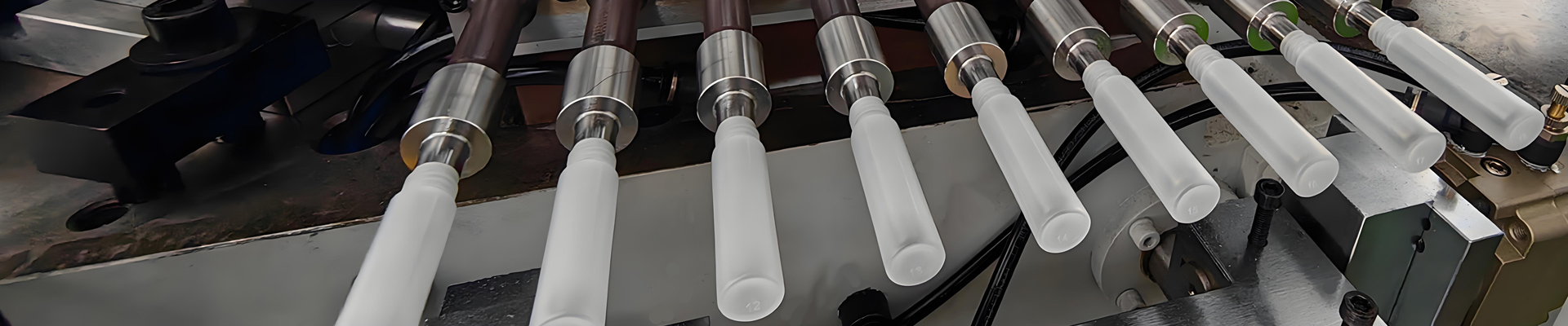
One-step injection blow molding has neither of these correction tools. The parison is injected onto a core rod, held on that rod, indexed to the blow station while still hot, and inflated using nothing but the residual heat from injection. There is no die gap program and no reheat oven. The temperature distribution the parison carries out of the injection cavity, minus whatever it loses in transfer, is exactly the temperature distribution that governs inflation. This is why the window is the narrowest of the three routes, why the time available is the shortest, and why thermal history sensitivity is highest.
So sánh ba phương án về mặt nhiệt
| Thermal Characteristic | One-Step Injection Blow Molding | Extrusion Blow Molding | Two-Step Stretch Blow Molding |
|---|---|---|---|
| Parison origin | Injection molded on core rod | Continuously extruded tube | Injection molded, cooled, stored |
| Reheat stage available | None | None | Yes, zoned infrared oven |
| Wall correction tool | Thermal only (core rod and cavity) | Mechanical (die gap programming) | Thermal (lamp zones) plus stretch rod |
| Typical usable temperature window | Narrow, roughly 8–20 degrees Celsius | Moderate, roughly 20–40 degrees Celsius | Wide, roughly 15–35 degrees Celsius with zoning |
| Time from forming to inflation | Under 3 seconds | Under 2 seconds | Hours to weeks, then controlled reheat |
| Sensitivity to thermal history | Very high | Moderate | Low, history is reset by reheat |
| Inner wall temperature governed by | Core rod circuit | Internal air, largely uncontrolled | Infrared penetration depth |
| Outer wall temperature governed by | Injection cavity circuit | Ambient and mold contact | Lamp output and air cooling |
| Scrap route for a bad parison | None, it becomes a bad bottle | Pinch-off flash trimming | Preform rejected before blowing |
The last row deserves emphasis. In two-step processing, a defective preform can be sorted out before it ever reaches a blow machine. In one-step injection blow molding, the parison and the bottle are the same production event. A thermal fault does not create a rejected intermediate; it creates a rejected finished container, with the full material and energy cost already spent. Temperature control in this process is therefore also the primary scrap control mechanism.
There is a second consequence that is easy to overlook. Because the parison never leaves the core rod, the core rod is a permanent thermal partner to the polymer. It is in contact with the inner wall during injection, during holding, during transfer, and during inflation. Any temperature non-uniformity along or around the core rod is imprinted onto the parison twice — once as a skin thickness gradient during injection, and again as a viscosity gradient during inflation. This double imprint is why core rod temperature control receives its own extended section later in this guide.
Chuỗi nhiệt độ hoàn chỉnh: Bảy mắt xích, một kết quả
Nhiệt độ parison không được thiết lập bởi một bộ điều khiển duy nhất. Nó là kết quả tích lũy của bảy mắt xích nhiệt tuần tự, mỗi mắt xích có điểm đặt riêng, vòng điều khiển riêng và chế độ hỏng hóc riêng. Xử lý bất kỳ một trong số chúng một cách riêng lẻ là nguyên nhân phổ biến nhất của các chương trình chai không ổn định.
Tổng quan chuỗi và quyền kiểm soát
| # | Link | Typical Control Range | Control Authority Over Parison | Primary Effect if Wrong |
|---|---|---|---|---|
| 1 | Resin drying and moisture | Ambient to 170 degrees Celsius, 2–6 h | Indirect but decisive | Hydrolysis, splay, strength loss |
| 2 | Barrel zones and nozzle | 170–300 degrees Celsius by material | Sets bulk melt enthalpy | Degradation or unmelted core |
| 3 | Hot runner and manifold | Melt setpoint, tolerance within 2 degrees Celsius | Cavity-to-cavity balance | Weight spread between cavities |
| 4 | Core rod circuit | 60–120 degrees Celsius, oil | Inner wall temperature, highest authority | Wall eccentricity, bottle lean |
| 5 | Injection cavity circuit | 20–90 degrees Celsius, water or oil | Outer skin thickness and gloss | Surface defects, sticking |
| 6 | Transfer path and dwell | 0.8–2.5 s exposure | Surface loss only | Shoulder freeze, cold blow |
| 7 | Blow cavity circuit | 5–70 degrees Celsius | Final set and crystallinity | Shrinkage spread, dimension drift |
Two structural insights follow from this table. First, control authority is not evenly distributed. The core rod circuit has more influence on wall distribution than any other link, because it governs the inner surface of a thin-walled tube where the temperature gradient across the wall is steep. Second, the links are not independent. Raising melt temperature to fix a cold shoulder will also raise the load on the core rod circuit, which may then run above its setpoint and cause sticking. Every adjustment should be evaluated as a change to the whole chain.
A practical rule our commissioning engineers apply: adjust the chain from the outside in. Confirm drying first, then barrel and nozzle, then hot runner balance, then core rod, then cavity, and only then consider transfer and blow mold. Working in the reverse direction — chasing a shoulder defect by changing blow mold temperature when the real cause is a hot runner imbalance — produces recipes that work for one shift and fail on the next.
Mắt xích 1: Nhiệt độ sấy nhựa và hàm lượng ẩm
Drying is a temperature parameter even though it happens before the machine. Residual moisture changes melt viscosity, changes the effective melt temperature needed to fill the parison, and in condensation polymers permanently reduces molecular weight through hydrolysis. A hydrolyzed parison behaves as if it were ten to twenty degrees hotter than the thermocouple says, because its viscosity has collapsed — and no amount of temperature adjustment restores the lost molecular weight.
The resins processed on injection blow molding lines split cleanly into three groups. Polyolefins and styrenics are non-hygroscopic or only surface-wetting, and require little or no drying. Amorphous engineering resins such as polycarbonate are hygroscopic and require dehumidified drying. Condensation polymers such as polyester and polyamide are strongly hygroscopic and require both dehumidified drying and a controlled dew point.
Thông số sấy theo nhóm nhựa
| Resin | Drying Temperature | Drying Time | Target Moisture | Dryer Type / Dew Point | Hydrolysis Risk |
|---|---|---|---|---|---|
| PP homopolymer and copolymer | Not required; 80 degrees Celsius if surface wet | 1–2 h optional | Below 0.05 percent | Hot air sufficient | None |
| HDPE / LDPE / LLDPE | Not required; 70–80 degrees Celsius if stored cold | 1–2 h optional | Below 0.05 percent | Hot air sufficient | None |
| PS (general purpose) | 70–80 degrees Celsius | 2 h | Below 0.05 percent | Hot air acceptable | None |
| SAN | 80 degrees Celsius | 2–3 h | Below 0.05 percent | Dehumidifying preferred | Low |
| ABS | 80–90 degrees Celsius | 2–4 h | Below 0.05 percent | Dehumidifying, dew point below minus 20 | Low |
| PETG / PCTG | 65 degrees Celsius (below sticking point) | 4 h | Below 0.02 percent | Dehumidifying, dew point minus 40 | High |
| PET | 160–170 degrees Celsius after crystallizing | 4–6 h | Below 0.005 percent (50 ppm) | Dehumidifying, dew point minus 40 | Very high |
| PC | 120 degrees Celsius | 3–4 h | Below 0.02 percent | Dehumidifying, dew point minus 30 | High |
| PA (polyamide 6) | 80 degrees Celsius, sealed transfer | 4–8 h | Below 0.10 percent (grade dependent) | Dehumidifying or vacuum, dew point minus 30 | Very high, reabsorbs in minutes |
| TPU | 80–100 degrees Celsius | 2–3 h | Below 0.03 percent | Dehumidifying, dew point minus 30 | High |
Three practical warnings follow from this table. First, polyester grades must be crystallized before high-temperature drying, otherwise pellets agglomerate in the hopper and starve the feed throat, producing an intermittent melt temperature that no barrel controller can smooth out. Second, polyamide reabsorbs atmospheric moisture within minutes of leaving the dryer; the transfer line from dryer to feed throat must be closed, and hopper residence at the machine should be minimized. Third, glycol-modified polyester cannot be dried at the temperature used for standard polyester, because it softens and blocks; sixty-five degrees Celsius with a long residence is the correct approach.
How does moisture show up as a parison temperature problem? Moisture flashes to steam in the barrel and hot runner. That steam creates two effects on the parison: microscopic voids and silver streaking on the surface, and a local reduction in viscosity that behaves exactly like an overheated zone. Technicians frequently respond by lowering melt temperature, which then produces unmelted material and a cold, stiff parison. The recipe oscillates and never settles. The diagnostic test is straightforward: purge material at the nozzle onto a clean surface and inspect for bubbling and crackling. If the purge foams, the problem is water, not temperature.
Moisture content should be verified, not assumed. A moisture analyzer reading taken at the feed throat, not at the dryer outlet, is the meaningful number. Dryers with degraded desiccant beds routinely show a correct outlet air temperature while delivering a dew point twenty or thirty degrees above specification, and the only way to detect this is measurement of the return air dew point plus periodic pellet testing.
Mắt xích 2: Hồ sơ vùng trục vít, vòi phun và áp suất ngược
The barrel converts solid pellets into a homogeneous melt at a controlled temperature. In injection blow molding the shot sizes are small — typically forty to one hundred fifty grams — which means residence time in the barrel is longer relative to shot volume than on a large injection molding machine. Long residence at high temperature is the fastest path to thermal degradation, so barrel profiles for injection blow molding are usually flatter and slightly cooler than the equivalent profile for a large part.
Logic thiết kế cấu hình vùng xi lanh
| Zone | Relative Setpoint | Function | Symptom if Too Low | Symptom if Too High |
|---|---|---|---|---|
| Feed throat (water cooled) | 25–50 degrees Celsius | Prevents pellet bridging | Condensation on pellets | Bridging, surging feed |
| Feed zone (rear) | Melt setpoint minus 25 to 35 | Conveys and preheats solids | Screw slip, inconsistent metering | Early melting, feed instability |
| Compression zone (middle) | Melt setpoint minus 10 to 20 | Melts and compacts | Unmelted core, cold slugs | Shear overheating |
| Metering zone (front) | Melt setpoint | Homogenizes and pressurizes | Uneven melt temperature | Degradation, discoloration |
| Nozzle | Melt setpoint minus 5 to plus 5 | Delivers to hot runner | Cold slug, gate blockage | Drooling, stringing |
The nozzle deserves special attention in a three-station machine. Because the injection unit indexes against the manifold repeatedly and the melt path is short, a nozzle running five degrees cold produces a cold slug that is injected into the first cavity of every shot. The result is a single cavity that consistently blows differently from its neighbors — a defect that operators often blame on the mold. Set the nozzle at or very slightly below the metering zone setpoint, and confirm by purging that the first material out is homogeneous and free of hard fragments.
Back pressure is a temperature parameter, not just a pressure parameter. Every additional bar of back pressure increases the work done on the melt during screw recovery, raising actual melt temperature above the barrel setpoint. For injection blow molding, typical back pressure sits between three and ten bar specific pressure. Below three bar, melt homogeneity suffers and unmixed colorant produces streaked parisons. Above ten bar on a small shot, shear heating can add ten to fifteen degrees Celsius to the melt without any change on the controller display — a classic reason for parisons that sag despite apparently correct settings.
Screw rotation speed acts the same way. On small-diameter screws, surface speed rises quickly with rotational speed, and shear heating with it. A practical guideline for injection blow molding is to keep screw surface speed below roughly 0.25 meters per second for shear-sensitive resins such as polyvinyl-free rigid grades, glycol-modified polyester and polyamide, and below roughly 0.4 meters per second for polyolefins. When the recovery must be faster, increase the screw diameter rather than the speed.
Actual melt temperature should be verified rather than trusted. Take a purge into an insulated container and immediately probe it with a fast-response needle pyrometer, or use a melt thermocouple in the nozzle adapter. A discrepancy of more than eight degrees between the display and the measured melt indicates that shear input, residence time or thermocouple placement needs review.
Mắt xích 3: Cân bằng kênh dẫn nóng và độ đồng đều giữa các khoang
Every injection blow molding mold above one cavity is a multi-cavity balancing problem, and the hot runner is where that balance is won or lost. The manifold splits one melt stream into four, six, eight, twelve or more drops. Each drop must deliver the same mass at the same temperature at the same moment. If it does not, cavity weight spreads, and because inflation is driven by residual heat, weight spread becomes wall thickness spread and then volume spread in the finished bottle.
The working tolerance we specify for injection blow molding hot runners is tighter than for general injection molding: individual drop temperatures should hold within two degrees Celsius of setpoint, and the spread across all drops should not exceed four degrees Celsius. The reason is the absence of a reheat correction stage. In two-step processing, a four-degree preform spread is largely erased in the oven. Here, it travels straight into the blow station.
Các mục tiêu điều khiển kênh dẫn nóng
| Item | Target | Verification Method | Consequence of Drift |
|---|---|---|---|
| Individual drop deviation | Within 2 degrees Celsius of setpoint | Controller trend log over 30 minutes | Single-cavity weight offset |
| Drop-to-drop spread | Below 4 degrees Celsius across all zones | Compare all zone actuals at steady state | Systematic wall thickness spread |
| Manifold-to-drop offset | Manifold at or 5 degrees below drop setpoint | Zone map review | Gate freeze or drool |
| Cavity weight variation | Coefficient of variation below 1.5 percent | Weigh all cavities, 10 consecutive shots | Volume non-conformance |
| Gate vestige consistency | Visually uniform across cavities | Optical inspection of base | Base stress, leak risk |
| Soft start ramp | 3–5 degrees Celsius per minute below 150 degrees | Controller startup profile | Heater cracking from trapped moisture |
| Thermocouple integrity | All zones reading within 3 degrees when cold | Cold-state cross-check before heating | Runaway zone, burnt material |
The cold cross-check in the last row is one of the highest-value five-minute procedures in the whole process. Before switching a hot runner on, read every zone with the mold at ambient temperature. All zones should read within about three degrees of each other and of room temperature. A zone reading fifteen degrees high when everything is cold has a damaged thermocouple, and once heating starts that zone will be under-powered while the controller believes it is on target. Material in that drop runs cold, that cavity underfills, and the operator spends the shift chasing an imaginary mold problem.
Flow balance is geometric as well as thermal. A naturally balanced manifold, in which every flow path from sprue to gate has identical length and identical cross-section, is strongly preferred for injection blow molding. Where geometry forces an artificially balanced layout with different channel diameters, the thermal tolerance must be tightened further, because temperature differences and flow-length differences compound rather than cancel. When commissioning a new mold, always perform a short-shot study first: run progressively larger shots and photograph the fill pattern. All cavities should reach the same fill percentage at the same shot size. If cavity three consistently lags, fix the balance before touching any temperature setting.
Gate design interacts with temperature as well. Injection blow molding typically uses a gate at the base of the parison. A gate that runs too hot leaves a soft, proud vestige that can create a leak path or a stress concentration in the finished base; a gate that runs too cold freezes early, cuts holding pressure short, and leaves a thin, under-packed base that later shows up as a low-volume bottle. Gate zone temperature should be trimmed in two-degree steps and evaluated against base vestige appearance and bottle weight together, never against appearance alone.
Mắt xích 4: Nhiệt độ trục lõi, biến số chính thực sự
If a reader takes only one section from this guide, it should be this one. The core rod determines the inner wall temperature of the parison, and the inner wall is where inflation begins. When air enters, the material closest to the core rod is the material that must yield first and stretch furthest. Its temperature therefore sets the entire inflation behavior of the bottle.
A core rod is not a passive mandrel. It is a temperature-controlled tool with an internal fluid circuit, typically supplied by an oil temperature controller running between sixty and one hundred twenty degrees Celsius depending on resin. It receives heat from the melt during injection, sheds heat to its circuit during holding and transfer, and receives heat again on the next shot. In steady state it reaches a thermal equilibrium — but only if the circuit design, the flow rate and the controller capacity all support it.
Điểm đặt nhiệt độ thanh lõi và ảnh hưởng
| Resin Group | Core Rod Setpoint | Medium | If Set 10 Degrees Low | If Set 10 Degrees High |
|---|---|---|---|---|
| LDPE / LLDPE | 45–70 degrees Celsius | Water or oil | Stiff inner skin, poor shoulder fill | Parison sag, rod sticking |
| HDPE | 50–80 degrees Celsius | Oil preferred | Whitening at expansion zone | Neck deformation on stripping |
| PP homopolymer | 60–90 degrees Celsius | Oil | Poor clarity, brittle base | Tacky surface, long set time |
| PS / SAN | 60–100 degrees Celsius | Oil | Stress lines, crazing on inflation | Surface drag marks on stripping |
| ABS | 70–100 degrees Celsius | Oil | Dull surface, weak shoulder | Gloss loss, sticking |
| PETG / PCTG | 80–115 degrees Celsius | Oil | Haze from strain whitening | Excessive sag, thin shoulder |
| PC | 100–120 degrees Celsius | Oil, high temperature rated | Molded-in stress, cracking | Neck softening, stripping damage |
| PA | 80–110 degrees Celsius | Oil | Incomplete inflation | Crystallization control loss |
| TPU | 50–80 degrees Celsius | Oil | Stiff, uneven expansion | Severe tackiness, stripping failure |
Thiết kế mạch bên trong thanh lõi
Trục lõi cho chai nhỏ thì mảnh — thường có đường kính từ tám đến hai mươi milimét — và phải mang một mạch chất lỏng dọc theo chiều dài và quay trở lại. Ba thiết kế bên trong là phổ biến và chúng hoạt động rất khác nhau.
The bubbler design uses a central inlet tube that discharges near the rod tip, with return flow in the surrounding annulus. It is compact and works well in very slender rods. Its weakness is that the tip runs cooler than the root because incoming fluid is at its coldest there, producing a rod that is coolest at the base of the bottle and warmest at the neck. For most bottle shapes this is actually beneficial, since the base needs less stretch, but it must be verified rather than assumed.
The spiral or helical channel design wraps the flow around the rod axis, giving the most uniform circumferential temperature. It requires a larger rod diameter and more complex machining, so it appears on larger containers and on high-precision cosmetic bottles where circumferential uniformity is critical.
The straight-drilled parallel channel design uses two or more longitudinal drillings connected at the tip. It is the simplest to manufacture but has the greatest circumferential variation, because the material directly above a channel runs cooler than the material between channels. On thin-walled parisons this variation prints through as a periodic wall thickness pattern visible when the bottle is sectioned.
Chênh lệch nhiệt độ thanh lõi và độ lệch tâm thành
Wall eccentricity is the defect that injection blow molders fight most often, and core rod temperature differential is its most common cause. The mechanism is straightforward. Polymer viscosity falls sharply with temperature — for most of these resins, a ten-degree rise reduces viscosity by roughly twenty to forty percent. If one side of the core rod runs five degrees warmer than the other, the polymer on the warm side yields earlier and stretches further during inflation. The parison inflates asymmetrically, the warm side thins, and the finished bottle has a thin wall on one side and a thick wall on the other. In severe cases the bottle leans visibly.
Mục tiêu dung sai chênh lệch của trục lõi
| Measurement | Target | Acceptable Limit | Typical Consequence at Limit |
|---|---|---|---|
| Circumferential differential, one rod | Below 2 degrees Celsius | 3 degrees Celsius | Wall eccentricity approaching 15 percent |
| Axial differential, tip to root | Below 8 degrees Celsius | 12 degrees Celsius | Shoulder-to-base thickness imbalance |
| Rod-to-rod spread across mold | Below 3 degrees Celsius | 5 degrees Celsius | Cavity-to-cavity volume spread |
| Circuit inlet-to-outlet delta | 3–6 degrees Celsius | 8 degrees Celsius | Insufficient flow, unstable control |
| Oil flow per rod circuit | Turbulent, Reynolds above 4000 | Laminar flow not acceptable | Poor heat transfer, slow response |
| Warm-up time to steady state | 20–40 minutes | Above 60 minutes indicates undersized unit | Long startup scrap run |
The inlet-to-outlet delta target deserves comment. A delta of three to six degrees Celsius across the rod circuit indicates that flow is high enough to carry heat away without letting the fluid warm significantly along its path. A delta of twelve degrees means flow is too low; the fluid is heating up as it travels, so the far end of the circuit is systematically warmer, and the rod develops exactly the axial differential we are trying to avoid. When a rod shows a large delta, the answer is more flow, not a lower setpoint. Lowering the setpoint moves the whole rod down without fixing the gradient.
Verifying circumferential uniformity requires a measurement discipline. With the machine stopped at a safe state and the rod exposed, take infrared readings at four points around the circumference — zero, ninety, one hundred eighty and two hundred seventy degrees — at three heights along the rod. That is twelve readings per rod. Record them in a fixed sheet so the same points are measured every time. Because infrared readings on polished steel are unreliable, apply a small patch of high-emissivity matte tape or matte paint at each measurement point and set the instrument emissivity accordingly, or use a contact probe. A polished core rod read directly with an infrared thermometer at default emissivity can easily read thirty degrees below its true temperature.
One more mechanism is worth noting. Core rods accumulate a thin polymer film over long runs, particularly with tacky resins. That film is an insulating layer, and it grows unevenly. A rod that measured within two degrees on Monday may show a five-degree differential on Friday purely because of film build-up. Scheduled rod cleaning is therefore a temperature control activity, not a housekeeping activity, and should appear on the process control plan with a defined interval based on resin and observed drift.
Mắt xích 5: Nhiệt độ khoang ép phun và hình thành lớp bề mặt
The injection cavity forms the outer surface of the parison. Where the core rod governs how the parison inflates from the inside, the cavity governs the skin: how thick the frozen layer is when the parison leaves the station, how glossy the surface is, and how much heat the parison retains in its outer third.
Cavity temperature ranges from about twenty degrees Celsius for chilled amorphous polyester work up to ninety degrees Celsius for polycarbonate. The setpoint is a compromise between two competing goals. A colder cavity produces a thicker frozen skin, which makes the parison mechanically stable and easy to handle but resistant to inflation and prone to strain whitening. A warmer cavity leaves a thinner skin, which inflates smoothly and gives excellent surface reproduction but risks sagging, sticking and distortion during stripping.
Ảnh hưởng của nhiệt độ lòng khuôn phun
| Cavity Temperature Direction | Skin Thickness | Surface Finish | Inflation Behavior | Risk |
|---|---|---|---|---|
| Low end of window | Thick, rigid | Matte, may show flow lines | Resists inflation, high pressure needed | Strain whitening, shoulder starvation |
| Mid window | Balanced | Consistent, good detail | Even, predictable | Low, target condition |
| High end of window | Thin, soft | High gloss, sharp detail | Easy inflation, low pressure | Sag, sticking, dimensional drift |
| Uneven across cavity | Variable | Patchy gloss | Asymmetric | Neck ovality, bottle lean |
Neck finish quality is the most temperature-sensitive feature on the whole container. In injection blow molding the neck is fully formed at the injection station and is not reblown — that is the process’s main advantage over extrusion blow molding, which must trim and calibrate the neck. To keep that advantage, the neck region of the cavity must run at a stable, slightly cooler temperature than the body region, so that thread geometry and sealing surface are fully set before the parison indexes. When a program shows neck ovality or inconsistent cap torque, the first place to look is the neck-area cooling circuit, not the blow station.
Cavity circuits should be laid out with the same turbulence requirement as core rods. Flow per circuit should be sufficient to reach turbulent conditions, which for typical eight to twelve millimeter circuits means roughly eight to twenty liters per minute depending on medium and temperature. Circuits should be connected in parallel rather than in a long series loop; a series loop that passes through the neck area, then the body, then the base develops a progressive temperature rise that guarantees an axial gradient.
For glycol-modified polyester and standard polyester, the cavity has an additional job: quenching. These resins crystallize if held in their crystallization temperature range, and a crystallized parison is opaque, brittle and unblowable. The cavity must remove heat fast enough to carry the outer layer through the crystallization range and into the amorphous state. This is why polyester work uses a chilled cavity at twenty to thirty degrees Celsius while simultaneously running a hot core rod at ninety to one hundred fifteen degrees Celsius — a deliberately large gradient across the parison wall that would be considered a fault with any other resin family.
Mắt xích 6: Mất nhiệt trong quá trình chuyển giữa các trạm
Between the injection station and the blow station, the parison is exposed. It sits on its core rod, indexing through open air, radiating and convecting heat from its outer surface. This transfer interval is short — typically between eight tenths of a second and two and a half seconds on a three-station machine — but the surface temperature loss during it is large enough to change the outcome.
The physics favor the surface. The parison’s outer skin is a thin layer with low thermal mass and direct exposure to ambient air; it can lose heat at rates between three and twelve degrees Celsius per second depending on air movement, ambient temperature and wall thickness. The core of the wall, insulated by the polymer itself and warmed from inside by the core rod, loses very little in the same interval. The result is that transfer sharpens the temperature gradient across the wall rather than simply lowering the whole parison.
Các yếu tố tổn thất nhiệt truyền
| Factor | Typical Value | Effect on Surface Temperature | Control Action |
|---|---|---|---|
| Transfer duration | 0.8–2.5 s | Loss scales roughly linearly | Keep index motion smooth and repeatable |
| Ambient workshop temperature | 18–35 degrees Celsius | Each 10 degrees lower adds roughly 10–15 percent loss | Control workshop climate, avoid seasonal drift |
| Forced air movement near machine | Highly variable | Can double surface loss rate | Shield the transfer path from fans and doorways |
| Parison wall thickness | 1.5–4.0 mm | Thin walls cool faster and deeper | Adjust core rod setpoint for thin-wall programs |
| Surface area to volume ratio | Higher on small bottles | Small parisons lose proportionally more | Run small containers at upper core rod range |
| Resin thermal conductivity | 0.15–0.35 W per meter kelvin | Polyolefins re-equalize faster than styrenics | Allow shorter dwell for polyolefins |
| Radiant environment near path | Hot manifold nearby raises local ambient | Reduces loss on one side only | Watch for one-sided thickness bias |
The last row is a real and frequently missed problem. If the transfer path passes close to a hot manifold or a heated component on one side only, the parison loses less heat on that side. The asymmetry is small — often two or three degrees — but as established in the core rod section, two or three degrees is enough to produce measurable wall eccentricity. When a bottle shows a consistent thin side that does not move when core rods are rotated or swapped, the cause is usually environmental asymmetry along the transfer path rather than the tooling.
Seasonal drift is the other classic transfer problem. A recipe developed in a warm workshop in summer will run cold in the same workshop in winter, because ambient temperature and door-draft patterns change. The parison arrives at the blow station several degrees cooler, inflation becomes sluggish, and the shoulder starves. Facilities that maintain workshop temperature within a few degrees year-round see dramatically fewer seasonal recipe adjustments. Where climate control is not practical, the process control plan should include an ambient temperature log alongside the process parameters, so the correlation is visible rather than mysterious.
Note also what transfer heat loss is not. It is not a reason to shorten the index motion beyond what the machine and mold safely allow. The correct response to excessive transfer loss is to raise the core rod setpoint slightly, shield the path, and stabilize the ambient, not to force a faster motion that compromises repeatability. Motion repeatability matters more than motion speed here: a transfer that varies between one and two seconds shot to shot produces a parison temperature that varies shot to shot, and that variation shows up directly as bottle weight and volume scatter.
Mắt xích bảy: Nhiệt độ khuôn thổi và định hình cuối
The blow cavity is where the container takes its final dimensions and where residual heat is finally removed. Its temperature setpoint controls three outcomes: how fast the wall sets against the cavity surface, how much the container shrinks after ejection, and — for semi-crystalline resins — how much crystallinity develops in the wall.
Blow mold temperature ranges from about five degrees Celsius for polyolefin work up to seventy degrees Celsius for polycarbonate. Colder is not automatically better. A very cold blow cavity freezes the surface on contact before the parison has fully conformed to the cavity detail, producing poor definition on embossed logos, weak neck-to-shoulder transitions and visible chill marks. A warmer cavity gives excellent surface reproduction and lower molded-in stress but requires more time for the wall to reach dimensional stability, and — critically for polypropylene and polyethylene — allows more crystallinity to develop.
Nhiệt độ khuôn thổi theo mục tiêu
| Objective | Blow Mold Direction | Mechanism | Trade-off Accepted |
|---|---|---|---|
| Maximum clarity in PP | Cold, 5–12 degrees Celsius | Quench limits spherulite growth | Higher post-mold shrinkage |
| Maximum dimensional stability | Moderate, 20–35 degrees Celsius | Allows controlled crystallization | Slightly reduced clarity |
| Best surface gloss and detail | Warm, 35–55 degrees Celsius | Delays skin freeze, improves contact | Longer set requirement |
| Lowest molded-in stress in PC | Warm, 45–70 degrees Celsius | Reduces frozen-in orientation | Higher energy demand |
| Amorphous set in PETG or PET | Cold, 8–20 degrees Celsius | Quench through crystallization range | Requires chiller capacity |
| Minimum shrinkage spread | Uniform circuits, tight tolerance | Even heat extraction | More complex mold cooling |
Crystallinity control is the deepest issue here. Polypropylene and polyethylene crystallize as they cool, and the rate of cooling determines both the degree of crystallinity and the size of the crystalline domains. Fast quenching in a cold blow cavity produces small domains and a clearer, more flexible bottle with somewhat higher post-mold shrinkage, because crystallization continues slowly at room temperature over the following hours. Slower cooling in a warmer cavity produces larger domains, a hazier and stiffer bottle, and lower post-mold shrinkage because most crystallization has already completed.
This is the reason a bottle can pass volume inspection at the machine and fail the same inspection twenty-four hours later. If the cavity was cold and the wall was quenched, the container keeps shrinking on the pallet. The correct engineering response is either to raise blow mold temperature so crystallization completes in the mold, or to define the volume specification against a container measured after a fixed conditioning period — commonly twenty-four hours at controlled room temperature. Both approaches are valid; what is not valid is comparing a fresh measurement against a specification derived from conditioned samples.
Blow mold circuits should be uniform and parallel, with attention to the base insert. The base of an injection blow molded bottle is generally the thickest section, because it is where the gate sits and where the least stretch occurs. A base insert with insufficient cooling holds heat, and that heat migrates outward after the container is ejected, producing localized post-mold distortion and, on standing bottles, a rocker base. If a program shows base instability, measure the base insert surface temperature during production and compare it with the body cavity surface; a difference above about eight degrees Celsius indicates the base circuit needs attention.
Dải nhiệt độ theo từng loại vật liệu
The following table consolidates working temperature windows for the resin families commonly processed on injection blow molding machines. These are engineering starting points for commissioning, not substitutes for the resin producer’s data sheet. Every grade within a family differs, and modified, filled or impact-toughened grades shift the window further.
Tài liệu tham khảo đầy đủ về dải nhiệt độ
| Material | Melt Temperature | Core Rod | Injection Cavity | Blow Mold | Sag Threshold | Cold Blow Threshold | Degradation Onset |
|---|---|---|---|---|---|---|---|
| PP homopolymer | 200–240 degrees Celsius | 60–90 | 40–70 | 8–20 | Core rod above 100 | Core rod below 50 | Above 260 with long residence |
| PP copolymer | 195–230 degrees Celsius | 55–85 | 35–65 | 8–18 | Core rod above 95 | Core rod below 45 | Above 250 |
| HDPE | 180–220 degrees Celsius | 50–80 | 30–60 | 5–18 | Core rod above 90 | Core rod below 40 | Above 250 |
| LDPE / LLDPE | 170–210 degrees Celsius | 45–70 | 25–50 | 5–15 | Core rod above 80 | Core rod below 35 | Above 240 |
| PS (general purpose) | 190–230 degrees Celsius | 60–95 | 40–65 | 15–30 | Core rod above 105 | Core rod below 50 | Above 250 |
| SAN | 210–250 degrees Celsius | 70–100 | 50–75 | 20–40 | Core rod above 110 | Core rod below 60 | Above 270 |
| ABS | 210–245 degrees Celsius | 70–100 | 50–80 | 25–45 | Core rod above 110 | Core rod below 60 | Above 265 |
| PETG / PCTG | 220–250 degrees Celsius | 80–115 | 20–40 | 8–20 | Core rod above 125 | Core rod below 70 | Above 265 |
| PET | 265–285 degrees Celsius | 95–120 | 8–25 | 8–20 | Core rod above 130 | Core rod below 85 | Above 295 |
| PC | 270–300 degrees Celsius | 100–120 | 80–100 | 45–70 | Core rod above 130 | Core rod below 90 | Above 320 |
| PA (polyamide 6) | 240–270 degrees Celsius | 80–110 | 60–90 | 30–60 | Core rod above 120 | Core rod below 70 | Above 290 |
| TPU | 180–215 degrees Celsius | 50–80 | 20–45 | 10–25 | Core rod above 90 | Core rod below 40 | Above 230 |
Reading this table correctly matters. The sag threshold and cold blow threshold columns are not absolute physical constants; they are the approximate core rod temperatures at which, with all other settings at mid-window, the corresponding defect begins to appear on a typical fifty to two hundred milliliter bottle with a two millimeter parison wall. Thinner walls, smaller containers and longer transfer times shift both thresholds upward, because the parison arrives cooler. Thicker walls and larger containers shift them downward.
Một vài lưu ý riêng theo vật liệu giúp hoàn thiện bức tranh.
Polypropylene is the workhorse of injection blow molding for cosmetic and pharmaceutical containers. Its window is comfortable and it tolerates a moderate degree of thermal drift, which is why new operations usually commission on polypropylene before moving to more demanding resins. Random copolymer grades give better clarity and a slightly lower window than homopolymer; clarified grades with nucleating agents improve clarity substantially but narrow the acceptable blow mold range, because the nucleating agent accelerates crystallization and quenching must be correspondingly faster.
Polyethylene grades inflate easily and forgive temperature error better than any other family, but they have the least dimensional stability and the highest post-mold shrinkage. High-density grades hold shape better; low-density grades give squeezable bottles at the cost of tighter tolerance control. Both have very low surface energy, which means printing or labeling requires surface treatment — a downstream consideration that is nonetheless affected by mold temperature, because a warmer mold produces a slightly higher surface crystallinity and marginally better ink adhesion.
Polystyrene and styrene-acrylonitrile are amorphous, so there is no crystallization to manage, but they are notch sensitive and prone to stress cracking. The temperature discipline here is about avoiding molded-in stress: a warmer core rod and a warmer blow mold reduce frozen-in orientation and improve environmental stress crack resistance, which matters when the container will hold alcohols, essential oils or fragrance formulations.
Glycol-modified polyester is the preferred resin for premium clear cosmetic bottles. Its behavior is governed by the need to remain amorphous, which drives the unusual combination of hot core rod and chilled cavity described earlier. It is also strongly hygroscopic, so the drying discipline from the first link is non-negotiable; hydrolyzed glycol-modified polyester loses viscosity dramatically and sags at settings that ran perfectly the previous day.
Standard polyester on a one-step injection blow molding machine without a stretch rod is the most demanding job in this list. Without biaxial stretching, the wall does not develop strain-induced crystallinity, so the container is weaker and less gas-barrier than a stretch-blown equivalent. It works for small pharmaceutical and diagnostic bottles where clarity matters more than barrier, but it requires excellent drying, precise melt control and aggressive cavity quenching. Where mechanical performance is the priority, an injection stretch blow molding configuration is the correct route.
Polycarbonate demands the highest temperatures of any resin in normal injection blow molding service and correspondingly the most robust thermal hardware — high-temperature oil circuits, well-insulated manifolds and heaters with adequate power density. Its reward is exceptional clarity, toughness and heat resistance, which is why it appears in reusable pharmaceutical and laboratory containers. Its punishment for poor drying is severe: hydrolyzed polycarbonate loses impact strength permanently, and the failure often does not appear until the container is dropped in the field.
Polyamide is used where chemical and barrier performance is required. It is the most aggressively hygroscopic material on the list, absorbing moisture from room air within minutes, and it crystallizes rapidly, which compresses the available inflation window. Successful polyamide work depends on a sealed material path from dryer to feed throat and a core rod running at the upper end of its range to keep the inner wall above the rapid crystallization region during transfer.
Thermoplastic polyurethane is soft, tacky and highly temperature sensitive. Its narrow window and strong tendency to stick to tooling mean that core rod temperature must be held with unusual precision, and surface treatment or specialized rod finishing is often required. The reward is a soft, resilient container for specialty cosmetic and medical applications that no rigid resin can match.
Bản đồ khuyết tật: Mỗi lỗi nhiệt độ trông như thế nào
Các lỗi nhiệt độ để lại những dấu vân tay đặc trưng. Học cách đọc chúng rút ngắn việc xử lý sự cố từ hàng giờ xuống vài phút. Bảng dưới đây ánh xạ sáu chế độ lỗi nhiệt độ chính với các triệu chứng nhìn thấy được và hành động khắc phục của chúng.
Bảng chẩn đoán khuyết tật nhiệt độ
| Error Mode | Visible Symptoms | Measurable Signature | Root Cause Candidates | Corrective Action |
|---|---|---|---|---|
| Parison overheated | Sag before blow, thin or perforated wall, rough surface, sticking to core rod, drool at gate | Weight low and falling, wall thinnest at shoulder, surface temperature above window | Melt too hot, core rod too hot, excessive back pressure, screw speed too high, residence too long | Lower metering zone in 5 degree steps, reduce back pressure, lower core rod 5 degrees, verify actual melt by purge probe |
| Parison too cold | Incomplete inflation, whitening at expansion zone, visible stress lines, thick base with starved shoulder, blunt detail | Weight high and stable, wall thickest at base, blow pressure demand rising | Core rod too cold, cavity too cold, long transfer, cold ambient, cold slug from nozzle | Raise core rod 5 degrees, raise cavity 5 degrees, shield transfer path, verify nozzle temperature |
| Core rod circumferential differential | Wall eccentricity, bottle leaning, one side consistently thin, uneven gloss band | Six-point wall measurement shows spread above 20 percent, differential above 3 degrees | Blocked or partially blocked circuit, laminar flow, polymer film build-up, channel design limitation | Flush circuit, raise flow to turbulent, clean rod, verify with 12-point infrared map |
| Core rod axial differential | Shoulder and base thickness imbalance, neck distortion, base rocker | Tip-to-root differential above 12 degrees, inlet-to-outlet delta above 8 degrees | Insufficient flow, undersized controller, bubbler tube depth wrong | Increase pump flow, upsize oil unit, verify bubbler discharge position |
| Cavity temperature non-uniformity | Inconsistent shrinkage, neck ovality, patchy gloss, cap torque variation | Cavity surface map shows spread above 5 degrees, volume spread across cavities | Series-connected circuits, scaled water passages, undersized chiller | Reconnect circuits in parallel, descale, verify chiller cooling capacity and pump flow |
| Hot runner drop imbalance | One or more cavities consistently light or heavy, gate vestige differences, single-cavity leakage | Cavity weight coefficient of variation above 1.5 percent, drop spread above 4 degrees | Failed thermocouple, degraded heater, unbalanced manifold geometry | Cold cross-check all zones, replace suspect thermocouple, perform short-shot balance study |
| Moisture masquerading as heat | Silver streaks, surface bubbles, random sag, inconsistent shot weight | Purge foams and crackles, moisture analyzer above target | Desiccant saturated, dew point high, hopper residence too short, open transfer line | Service dryer, verify return dew point, seal transfer line, extend drying time |
| Blow mold temperature error | Poor logo definition, chill marks, post-mold shrinkage drift, haze in clear resins | Volume measured fresh differs from 24-hour conditioned volume by more than 1 percent | Cavity too cold for detail, base insert underserved, crystallization incomplete | Raise blow mold to target crystallinity, improve base insert circuit, define conditioned inspection |
A caution on interpretation. Several of these signatures overlap. Thin shoulders appear both when the parison is too cold and when the core rod has an axial differential. The discriminator is the weight trend: an overall cold parison runs heavy and stable, while an axial differential produces normal total weight with abnormal distribution. Always weigh before adjusting. A digital balance with a resolution of one hundredth of a gram, used on ten consecutive shots per cavity, resolves most ambiguities within minutes and costs far less than a shift of guesswork.
A second caution concerns compensating errors. It is entirely possible to run acceptable bottles with a core rod ten degrees too hot and a cavity ten degrees too cold, because the two errors partly cancel. Such a recipe is fragile: any drift in either direction pushes the process out of tolerance immediately, and the recipe cannot be transferred to another machine or another mold. When taking over an unfamiliar program, it is worth verifying that each link sits inside its own window rather than only checking that the finished bottle passes.
Phần cứng kiểm soát nhiệt độ và thực hành đo lường
Kiểm soát nhiệt độ tốt là một câu hỏi phần cứng trước khi là câu hỏi cài đặt. Một bộ điều khiển không thể giữ một điểm đặt mà bộ gia nhiệt, cảm biến hoặc mạch làm mát của nó không thể hỗ trợ về mặt vật lý.
Cặp nhiệt điện: Loại, vị trí lắp đặt và độ sâu
Type J thermocouples, iron and constantan, are the standard for barrel and hot runner service in plastics processing, covering the range from zero to about seven hundred sixty degrees Celsius with good sensitivity. Type K, nickel-chromium and nickel-aluminum, extends higher and is used where a wider range is needed. What matters more than type is placement.
A thermocouple measures its own junction temperature, not the melt temperature. If the junction sits in a shallow well near the outside of a barrel, it reads a blend of heater band temperature and ambient, biased warm during heating and cold during cooling. The correct practice is a deep well with the junction close to the melt-contact surface — as a rule, insertion depth of at least ten times the probe diameter, with the tip within two to four millimeters of the bore. The probe must be spring-loaded or otherwise held in firm contact with the bottom of the well; an air gap of half a millimeter can introduce a reading error of ten degrees or more.
Hướng dẫn thông số kỹ thuật cảm biến và bộ gia nhiệt
| Component | Specification Guidance | Common Fault | Detection |
|---|---|---|---|
| Barrel thermocouple | Type J, deep well, tip 2–4 mm from bore, spring loaded | Shallow seating, air gap | Slow response, overshoot on startup |
| Hot runner drop thermocouple | Type J, integral to nozzle, close to gate | Broken junction reading high | Cold cross-check before heating |
| Barrel heater band | 3–6 watts per square centimeter | Loose clamping, hot spots | Infrared scan of band surface |
| Hot runner cartridge heater | 10–25 watts per square centimeter | Moisture ingress, open circuit | Resistance check when cold |
| Core rod oil circuit | Turbulent flow, Reynolds above 4000 | Partial blockage, laminar flow | Inlet-to-outlet delta above 8 degrees |
| Mold temperature controller | Sized for peak heat load with 30 percent margin | Undersized, cannot hold at rate | Actual lags setpoint under load |
| Chiller for blow mold | Cooling capacity matched to throughput and resin enthalpy | Fouled condenser, low charge | Water outlet temperature climbing |
| Thermal insulation plates | Between mold and platen, and around manifold | Missing or compressed | Platen temperature rising over shift |
Hiệu chỉnh PID và hành vi điều khiển
Modern temperature controllers offer auto-tuning, and for most zones the auto-tuned parameters are adequate. Where they are not, the symptoms are recognizable. A zone that oscillates around setpoint with a regular period has too much integral action or too much gain; reduce proportional gain first. A zone that approaches setpoint slowly and never quite arrives has too little integral action. A zone that overshoots dramatically on startup but is stable afterwards needs a soft-start ramp rather than different tuning.
Soft start matters particularly for hot runners. Cartridge heaters and manifold heaters absorb atmospheric moisture when the mold sits idle. Applying full power to a damp heater flashes that moisture to steam inside the heater sheath and cracks it. The standard protection is a ramped startup: hold below one hundred fifty degrees Celsius while rising at three to five degrees per minute, dwell for ten to fifteen minutes to bake out moisture, then proceed to setpoint. Every hot runner controller supports this; it is often disabled to save startup time, and the cost appears later as heater failures.
Thực hành xác minh bằng tia hồng ngoại
An infrared thermometer is the fastest way to verify tool surface temperatures, but it is also the easiest instrument to misuse. Three rules make it reliable. First, set emissivity correctly: polished steel has an emissivity around 0.1 to 0.2, which means an instrument set to the default 0.95 will read dramatically low. Apply matte tape or matte high-temperature paint patches at fixed measurement points and set emissivity to the value of that surface, typically around 0.95. Second, respect the distance-to-spot ratio: at a twelve-to-one ratio, measuring from sixty centimeters averages a five-centimeter spot, which on a slender core rod includes a great deal of background. Move close. Third, calibrate against a contact probe periodically — place both on the same matte patch on a stable warm surface and confirm agreement within two degrees.
For core rods specifically, a contact probe with a flat spring-loaded tip is more reliable than infrared, because rod surfaces are curved, polished and small. Where production schedules allow, the most accurate approach is to stop the machine at a safe state immediately after a production run and take contact readings within the first thirty seconds, before the rod equalizes.
Phương pháp chạy thử: Tìm và giữ cửa sổ quy trình
Một phương pháp có cấu trúc tìm ra cửa sổ nhiệt độ ổn định nhanh hơn kinh nghiệm đơn thuần, và — quan trọng hơn — tạo ra một cửa sổ được lập tài liệu có thể tái tạo trên ca khác, máy khác hoặc sau khi thay khuôn.
Bước Một: Thiết lập Đường cơ sở và Xác minh Phần cứng
Before touching any setpoint, verify the hardware. Cold cross-check all thermocouples. Confirm oil and water circuits reach turbulent flow with acceptable inlet-to-outlet deltas. Confirm the dryer is delivering the specified dew point and that pellet moisture at the feed throat meets the target. Confirm heater resistances. Record ambient workshop temperature. Roughly one commissioning problem in three is resolved at this stage without any process adjustment at all.
Bước hai: Thiết lập chuỗi từ dữ liệu vật liệu
Đặt mỗi mắt xích ở điểm giữa của cửa sổ của nó từ bảng vật liệu. Đừng cố bắt đầu ở một điều kiện đã được tối ưu hóa; hãy bắt đầu ở tâm để có không gian di chuyển theo cả hai hướng. Cho phép máy đạt trạng thái ổn định — hai mươi đến bốn mươi phút cho các mạch dầu, lâu hơn cho các khuôn lớn.
Bước ba: Xác định trạng thái ổn định một cách khách quan
Steady state is not a feeling. Define it as twenty consecutive shots during which every controlled zone stays within one degree of its setpoint, total shot weight varies by less than one percent, and no visible drift appears in wall distribution. Until that condition is met, any experiment you run is measuring warm-up, not process response.
Bước Bốn: Thí nghiệm Nhiệt độ Đơn biến
Change one temperature at a time. Move it in a defined increment — five degrees Celsius is a good default for core rod and cavity, two degrees for hot runner drops — then wait for the tool to re-equalize before evaluating. Re-equalization takes longer than most operators expect: an oil-heated core rod needs eight to fifteen minutes to settle after a five-degree change, and evaluating after two minutes measures a transient rather than a new steady state. Record the increment, the wait, and the result in a fixed format.
Bước Năm: Đo Độ dày Thành tại Các Điểm Cố định
Wall thickness is the primary response variable. Measure at a minimum of six points per bottle: four around the circumference at mid-body, plus one at the shoulder and one at the base. For larger or complex containers, use eight to twelve points including a second circumferential ring. Use a magnetic wall thickness gauge or section the bottle and measure with a micrometer. Always measure the same points, marked on a template, so that data from different shifts is comparable.
Kế hoạch đo độ dày thành
| Point | Location | Primarily Reveals | Target Tolerance |
|---|---|---|---|
| P1–P4 | Mid-body at 0, 90, 180, 270 degrees | Core rod circumferential differential | Spread below 15 percent of mean |
| P5 | Shoulder transition | Parison temperature at inflation, transfer loss | Within 20 percent of mid-body mean |
| P6 | Base center, off gate | Gate temperature, axial differential | Within 40 percent above mid-body mean |
| P7–P8 (optional) | Upper body ring at 0 and 180 degrees | Axial gradient along core rod | Spread below 15 percent |
| Neck | Sealing surface and thread | Cavity neck circuit stability | Ovality within drawing tolerance |
Bước sáu: Kiểm soát biến thiên trọng lượng
Weight is the fastest and cheapest process indicator available. Weigh every cavity for ten consecutive shots and calculate the coefficient of variation. A well-controlled injection blow molding program holds total shot weight variation below one percent and cavity-to-cavity variation below one and a half percent. When variation exceeds these figures, the cause is almost always thermal — a drifting hot runner zone, an unstable core rod circuit, or moisture in the feed — rather than mechanical.
Bước bảy: Thiết lập kiểm soát quá trình bằng thống kê trên nhiệt độ
Once the window is found, the task becomes holding it. Log the key temperatures continuously and chart them. Most modern controllers export trend data; where they do not, a manual log at fixed intervals still works. The value of the chart is early warning: a hot runner zone that drifts one degree per week is invisible in a daily reading and obvious in a monthly trend, and it can be corrected before it produces scrap.
Kế hoạch giám sát nhiệt độ được khuyến nghị
| Parameter | Frequency | Method | Action Limit |
|---|---|---|---|
| All controller zone actuals | Continuous, reviewed each shift | Controller trend log | Deviation above 2 degrees from setpoint |
| Actual melt temperature | Weekly and after any resin change | Purge probe with needle pyrometer | Above 8 degrees from display |
| Core rod 12-point map | Monthly and after rod cleaning | Contact probe or matte-patch infrared | Circumferential spread above 3 degrees |
| Cavity surface map | Monthly | Infrared with emissivity patches | Spread above 5 degrees |
| Oil circuit inlet and outlet | Each shift | Controller display | Delta above 8 degrees |
| Pellet moisture at feed throat | Daily, each resin lot | Moisture analyzer | Above material target |
| Ambient workshop temperature | Each shift | Wall-mounted logger | Change above 5 degrees from baseline |
| Cavity weights | Each shift start and after changeover | Balance, 10 shots all cavities | Coefficient of variation above 1.5 percent |
| Conditioned volume check | Each lot | Water fill after 24 hours conditioning | Outside drawing tolerance |
One organizational point deserves mention. Temperature discipline fails most often at shift handover, when an incoming operator makes an adjustment without knowing what the outgoing operator changed. The countermeasure is a change log attached to the machine in which every setpoint change is recorded with time, magnitude, reason and observed result. This costs nothing and prevents the recipe drift that turns a well-commissioned program into a mystery within a few weeks.
Máy ép phun thổi chai Aibim
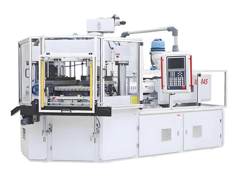
Aibim builds three-station one-step injection blow molding machines with independent temperature control across the injection, blow and stripper stations, covering containers from three milliliters to one thousand milliliters. Every machine ships with a multi-zone temperature control architecture designed around the chain described in this guide: barrel zones, nozzle, hot runner zones, core rod oil circuits, injection cavity circuits and blow cavity circuits are each independently controlled and independently logged.
Các dải thông số dưới đây là các cửa sổ kỹ thuật điển hình để thảo luận cấu hình. Các con số chính xác phụ thuộc vào số lòng khuôn, nhựa và hình dạng bao bì, và nên được xác nhận theo bảng dữ liệu nhà máy cho một dự án cụ thể.
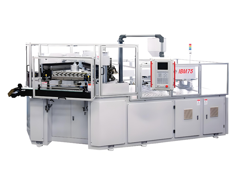
Máy ép phun thổi chai IBM75
The IBM75 is the largest machine in the range and the natural choice for larger cosmetic and pharmaceutical containers, thick-walled polycarbonate work, and programs where a high cavity count is needed on medium volumes. Its larger injection unit and greater clamping capacity give the thermal headroom required for high-temperature resins.
| Parameter | Typical Range |
|---|---|
| Model | IBM75 |
| Clamping force (kN) | 750 |
| Injection screw diameter (mm) | 45 |
| Shot size (g) | 80–150 |
| Container volume range (ml) | 50–1000 |
| Cavity count (typical) | 4–12 depending on container size |
| Stations | 3 (injection, blow, stripper) |
| Barrel temperature zones | 4 plus nozzle |
| Hot runner temperature zones | Up to 12, individually controlled |
| Kiểm soát nhiệt độ trục lõi | Oil circuit, 60–120 degrees Celsius |
| Injection cavity temperature control | Water or oil, 20–100 degrees Celsius |
| Blow cavity temperature control | Chilled water, 5–70 degrees Celsius |
| Installed power (kW) | 25–33 |
| Dry cycle time (s) | 10–16 |
| Processable materials | PE, PP, PS, ABS, SAN, TPU, PC, PCTG |
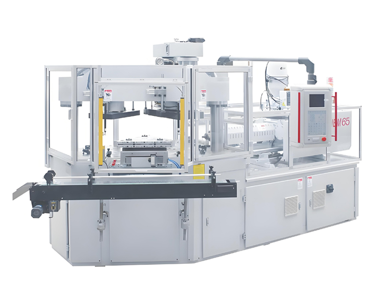
Máy ép phun thổi chai IBM65
The IBM65 is the volume workhorse of the range, covering the ten to five hundred milliliter band where most pharmaceutical and daily chemical containers sit. Its temperature architecture is identical in principle to the IBM75 but sized for faster thermal response, which suits high-cavitation molds running polyolefins and styrenics.
| Parameter | Typical Range |
|---|---|
| Model | IBM65 |
| Clamping force (kN) | 650 |
| Injection screw diameter (mm) | 40 |
| Shot size (g) | 60–110 |
| Container volume range (ml) | 10–500 |
| Cavity count (typical) | 6–16 depending on container size |
| Stations | 3 (injection, blow, stripper) |
| Barrel temperature zones | 4 plus nozzle |
| Hot runner temperature zones | Up to 16, individually controlled |
| Kiểm soát nhiệt độ trục lõi | Oil circuit, 60–115 degrees Celsius |
| Injection cavity temperature control | Water or oil, 20–90 degrees Celsius |
| Blow cavity temperature control | Chilled water, 5–60 degrees Celsius |
| Installed power (kW) | 18–25 |
| Dry cycle time (s) | 9–14 |
| Processable materials | PE, PP, PS, ABS, SAN, TPU, PC, PCTG |
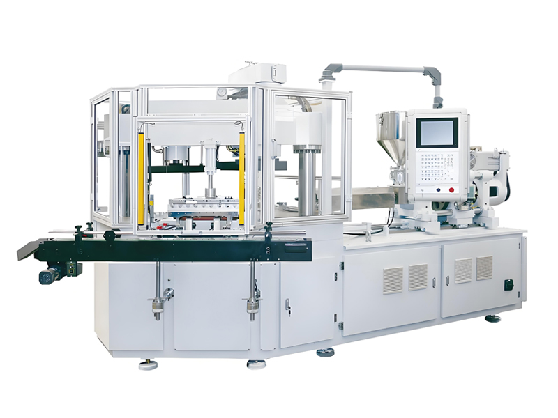
Máy ép phun thổi chai IBM55 lai điện-thủy lực
The IBM55 Hybrid Electric targets the smallest containers — three to two hundred fifty milliliters — where surface-to-volume ratio is highest and thermal control is therefore most critical. Electric servo motion on the primary axes reduces hydraulic oil heating, which in turn reduces one of the hidden sources of thermal drift on long runs: rising oil tank temperature that slowly changes the thermal environment of the whole machine.
| Parameter | Typical Range |
|---|---|
| Model | IBM55 Hybrid Electric |
| Clamping force (kN) | 550 |
| Injection screw diameter (mm) | 35 |
| Shot size (g) | 40–80 |
| Container volume range (ml) | 3–250 |
| Cavity count (typical) | 8–24 depending on container size |
| Stations | 3 (injection, blow, stripper) |
| Barrel temperature zones | 3 plus nozzle |
| Hot runner temperature zones | Up to 24, individually controlled |
| Kiểm soát nhiệt độ trục lõi | Oil circuit, 50–110 degrees Celsius |
| Injection cavity temperature control | Water or oil, 15–85 degrees Celsius |
| Blow cavity temperature control | Chilled water, 5–55 degrees Celsius |
| Installed power (kW) | 12–18 (hybrid, lower draw) |
| Dry cycle time (s) | 8–13 |
| Energy saving versus conventional hydraulic | Minimum 35 percent |
| Processable materials | PE, PP, PS, ABS, SAN, TPU, PC, PCTG |
All three series share the same core engineering features relevant to temperature control. The PREFILL hydraulic technology with variable displacement pump pressurizing reduces heat generation in the hydraulic circuit, limiting the machine-frame temperature rise that otherwise causes slow drift over an eight-hour run. The single-crossbeam, double-pole clamping framework provides enlarged mold setting space, which matters more than it sounds: generous space around the tool allows properly sized oil and water manifolds, insulation plates, and short hose runs, all of which improve temperature stability. SD card parameter storage lets a validated temperature recipe be captured and reinstalled on another machine, removing the recommissioning cycle when a program is transferred between lines. All machines are CE certified, with a long-distance digital laser sensor at the stripper station for mold protection and a light curtain for personal safety.
Các ngành ứng dụng và sản phẩm cuối
Máy Aibim phục vụ các ngành dược phẩm, thực phẩm, đồ uống và mỹ phẩm, và mỗi ngành đặt ra những yêu cầu khác nhau lên chuỗi nhiệt độ.
Cosmetic lotion and cream bottles in the thirty to two hundred milliliter range are typically molded in polypropylene, glycol-modified polyester or styrene-acrylonitrile. The driving requirement is surface quality: a visible defect on a cosmetic bottle is a rejected bottle regardless of function. This pushes cavity temperature toward the upper end of the window for gloss and detail, and demands very tight core rod circumferential uniformity because wall eccentricity shows immediately as an uneven light reflection along the bottle body.
Pharmaceutical solid-dose and oral liquid bottles from thirty to five hundred milliliters are usually high-density polyethylene, polypropylene or polycarbonate. Here the driving requirements are dimensional consistency of the neck for reliable child-resistant closure engagement, absence of molded-in stress that could lead to stress cracking in contact with the formulation, and full traceability of process conditions. Temperature logging is not merely good practice in this sector; it is part of the validation package. Materials for drug contact are commonly assessed against standards such as USP Class VI and ISO 10993, and the resin supplier’s documentation should be confirmed for the specific grade.
Eye drop and nasal spray bottles in the five to thirty milliliter range are among the most demanding parts in injection blow molding. They are small, thin-walled, and require an exceptionally precise neck and dropper interface. Their high surface-to-volume ratio means transfer heat loss is proportionally severe, so these programs typically run at the upper end of the core rod window with careful shielding of the transfer path. Low-density and high-density polyethylene dominate, with polypropylene where greater rigidity is wanted.
Probiotic and supplement mini bottles from three to twenty milliliters push cavity counts high — sixteen to twenty-four cavities is common — which makes hot runner balance the dominant quality variable. At these sizes, a single drop running three degrees cold produces a visibly different bottle, and the cavity weight coefficient of variation target should be tightened below one percent.
Fragrance and essential oil bottles demand chemical compatibility and clarity. Styrene-acrylonitrile and glycol-modified polyester are common, and molded-in stress control is critical because fragrance formulations are aggressive stress-cracking agents. This is a case where a warmer core rod and warmer blow mold are chosen deliberately, accepting slightly slower set in exchange for lower residual stress.
Diagnostic and reagent bottles for laboratory use are typically polypropylene, polycarbonate or polyethylene, sized from ten to five hundred milliliters. Requirements center on dimensional stability for automated handling equipment, leak integrity, and in some cases resistance to autoclaving, which drives material selection toward polypropylene and polycarbonate and requires a blow mold temperature high enough to complete crystallization so the container does not distort during sterilization.
Các vật liệu có thể gia công trong dòng sản phẩm Aibim bao gồm PE ở dạng mật độ cao, mật độ thấp và mật độ thấp tuyến tính, PP, PS, ABS, SAN, TPU, PC và PCTG.
Hướng dẫn lựa chọn: Từ yêu cầu đến model
Bảng dưới đây liên kết các yêu cầu điển hình với máy được khuyến nghị, số khoang và cấu hình kiểm soát nhiệt độ. Sử dụng nó làm điểm khởi đầu cho cuộc thảo luận cấu hình; lựa chọn cuối cùng phụ thuộc vào bản vẽ bao bì chính xác, cấp nhựa và sản lượng mục tiêu.
| Container Volume | Material | Target Output | Recommended Model | Cavity Count | Temperature Configuration |
|---|---|---|---|---|---|
| 3–15 ml | LDPE / HDPE | 4,000–7,000 pcs per hour | IBM55 Hybrid Electric | 16–24 | Core rod 55–70, cavity 25–45, blow mold 8–15 |
| 10–30 ml | PP homopolymer | 3,500–6,000 pcs per hour | IBM55 Hybrid Electric | 12–20 | Core rod 65–85, cavity 45–65, blow mold 8–18 |
| 20–60 ml | SAN / PS | 2,500–4,500 pcs per hour | IBM65 | 10–16 | Core rod 75–95, cavity 55–75, blow mold 20–35 |
| 30–120 ml | PETG / PCTG | 2,000–3,500 pcs per hour | IBM65 | 8–12 | Core rod 90–110, cavity 20–35 chilled, blow mold 8–18 |
| 50–200 ml | PP copolymer | 2,000–3,500 pcs per hour | IBM65 | 8–12 | Core rod 60–85, cavity 40–60, blow mold 10–20 |
| 60–250 ml | ABS | 1,500–2,800 pcs per hour | IBM65 | 6–10 | Core rod 80–100, cavity 55–80, blow mold 30–45 |
| 100–400 ml | HDPE | 1,500–2,500 pcs per hour | IBM75 | 6–10 | Core rod 55–80, cavity 35–60, blow mold 8–18 |
| 150–500 ml | PC | 900–1,600 pcs per hour | IBM75 | 4–8 | Core rod 105–120, cavity 85–100, blow mold 50–70 |
| 200–600 ml | PA | 800–1,500 pcs per hour | IBM75 | 4–8 | Core rod 90–110, cavity 65–90, blow mold 35–60 |
| 300–1000 ml | PP / HDPE | 700–1,400 pcs per hour | IBM75 | 4–6 | Core rod 60–85, cavity 40–70, blow mold 10–22 |
| 3–100 ml, soft feel | TPU | 1,200–2,500 pcs per hour | IBM55 Hybrid Electric | 8–16 | Core rod 55–75 tightly held, cavity 25–40, blow mold 12–22 |
Two notes on using this table. First, the output figures assume a well-commissioned program at steady state with a mature mold; a new program should be planned with margin. Second, the temperature configurations shown are mid-window starting points in degrees Celsius, intended to shorten the first day of commissioning, not to replace the single-variable experiments described earlier.
Dịch vụ và hỗ trợ
Aibim, với tư cách là nhà máy của Wanplas, áp dụng các cam kết dịch vụ của tập đoàn Wanplas, với chuỗi nhiệt độ được coi là một đối tượng cụ thể của thử nghiệm, đào tạo và hỗ trợ dài hạn.
Sampling and mold trials. Before a machine and mold package is finalized, we run sample trials with the customer’s resin grade and container drawing. The output of a trial is not only sample bottles but a documented temperature recipe: barrel profile, nozzle, every hot runner zone, core rod setpoint and measured differential, cavity setpoints, and blow mold setpoint, together with the wall thickness map and cavity weight data that validate them.
Factory acceptance testing for thermal stability. Machines are test-run and inspected before shipment. For temperature-critical programs we extend the acceptance protocol to include a thermal stability run: the machine holds production conditions while every zone actual is logged, and acceptance requires that all zones stay within tolerance of setpoint and that cavity weight variation remains inside the agreed limit for the duration. Customers are welcome to witness this testing at the factory.
Installation and commissioning. Engineers attend site for installation, commissioning and first production. The commissioning brief explicitly covers oil and water circuit connection, verification of turbulent flow, thermocouple cold cross-check, dryer dew point verification, and establishment of the initial temperature recipe on the customer’s own utilities — because a recipe validated on factory utilities is not automatically valid on a different chiller, a different oil unit, or a different workshop climate.
Spare parts policy. The Wanplas group policy provides USD 500 in free parts every year, plus free replacement for parts damaged within the warranty period. For temperature control this typically covers the consumable end of the chain: thermocouples, heater bands, cartridge heaters and seals, which are exactly the components whose gradual failure causes the slow thermal drift described throughout this guide.
Process training. Operator and technician training covers the diagnostic logic in this article: how to read a defect and identify which link of the chain is responsible, how to run a single-variable temperature experiment, how to map a core rod, how to interpret cavity weight data, and how to maintain a change log. Training is delivered during commissioning and can be repeated for new staff.
Remote support. Where a temperature problem appears after commissioning, our engineers work with site staff remotely, reviewing controller trend data, weight records and wall thickness maps to isolate the responsible link before deciding whether a site visit is required. Most thermal drift problems are resolved this way.
Nhà máy mở. Wanplas vận hành chính sách nhà máy mở trên toàn mạng lưới của mình. Khách hàng và khách hàng tiềm năng được chào đón đến tham quan, xem máy đang chạy thử và xem xét quy trình chạy thử nghiệm thu nhiệt trực tiếp.
Câu hỏi thường gặp
Nhiệt độ quan trọng nhất trong injection blow molding là gì?
Core rod temperature. The core rod governs the inner wall of the parison, which is the layer that must yield first and stretch furthest during inflation, so it has the greatest influence on wall distribution. A circumferential differential of only two to three degrees Celsius around a core rod is enough to produce visible wall eccentricity and, in extreme cases, a leaning bottle. Melt temperature and cavity temperature matter, but neither has the same direct authority over how the parison expands.
Tại sao chai của tôi có vai mỏng và đáy dày?
This is the classic signature of a parison that is too cold at the point of inflation, or of an axial temperature gradient along the core rod that leaves the upper region cooler than the lower region. Check total bottle weight first: if the bottle is heavy and the distribution is wrong, the parison is globally cold, and the fix is a higher core rod setpoint, a warmer cavity, or reduced transfer heat loss. If total weight is normal, the problem is distribution, and the fix is the core rod circuit — verify inlet-to-outlet delta and confirm turbulent flow.
Parison mất bao nhiêu nhiệt trong quá trình chuyển giữa các trạm?
Surface temperature loss during transfer typically runs between three and twelve degrees Celsius per second, depending on ambient temperature, air movement near the machine, parison wall thickness and container size. Over a transfer of one to two seconds, that means a surface loss of several to more than twenty degrees. The core of the wall loses far less, so transfer mainly sharpens the temperature gradient across the wall rather than cooling the parison uniformly. Small, thin-walled containers are affected most.
Dung sai nhiệt độ mà kênh dẫn nóng (hot runner) cần duy trì trong ép phun thổi là bao nhiêu?
Individual drop zones should hold within two degrees Celsius of setpoint, and the spread across all drops should stay below four degrees Celsius. This is tighter than typical general injection molding practice because the one-step process has no reheat stage to correct preform temperature differences. Any imbalance travels directly into the blow station and appears as cavity-to-cavity weight and wall thickness variation. Verify with a cold cross-check of all thermocouples before every startup.
Tôi có thể khắc phục sự cố nhiệt độ bằng cách thay đổi áp suất thổi hoặc thời gian thổi không?
Only superficially, and only within a very narrow range. Raising blow pressure can force a slightly cold parison to conform, but it does so by straining material that is below its optimal forming temperature, which introduces whitening, stress lines and reduced impact strength. Extending blow time gives the wall longer to set but does not change how the material distributed itself during inflation. Pressure and timing are for fine adjustment inside a correct temperature window, not for compensating a wrong one.
Tại sao chai của tôi đạt kiểm tra thể tích tại máy nhưng lại trượt vào ngày hôm sau?
Post-mold shrinkage. Semi-crystalline resins such as polypropylene and polyethylene continue to crystallize slowly at room temperature after ejection, and the container keeps shrinking for hours. If the blow mold ran cold and quenched the wall, most crystallization happens off the machine. There are two valid responses: raise blow mold temperature so crystallization completes in the mold, or define the volume specification against containers conditioned for a fixed period, commonly twenty-four hours at controlled room temperature.
Làm thế nào để đo nhiệt độ trục lõi một cách chính xác?
Use a contact probe with a flat spring-loaded tip where possible, because core rods are polished, curved and small, all of which defeat infrared measurement. If infrared must be used, apply matte high-temperature tape or paint patches at fixed measurement points and set instrument emissivity to match that surface; a polished rod read at default emissivity can appear thirty degrees cooler than it actually is. Take twelve readings per rod — four circumferential positions at three heights — and always measure the same marked points so data is comparable over time.
Độ ẩm của nhựa có thực sự ảnh hưởng đến hành vi nhiệt độ của phôi (parison) không?
Yes, and it is one of the most misdiagnosed problems in the process. Moisture flashes to steam in the barrel, causing local viscosity collapse that behaves exactly like an overheated zone, along with silver streaking and surface bubbles. Operators respond by lowering melt temperature, which then produces unmelted material and a stiff parison, and the recipe oscillates without ever settling. The quick test is to purge onto a clean surface: if the melt foams and crackles, the problem is water. Verify moisture at the feed throat, not at the dryer outlet.
Loại nhựa nào dễ chạy thử nhất trên dây chuyền injection blow molding mới?
Polypropylene homopolymer or random copolymer. It has a comfortable temperature window, requires little or no drying, tolerates moderate thermal drift, and produces containers suitable for cosmetic, pharmaceutical and food applications. Most new operations commission the line and train operators on polypropylene before moving to glycol-modified polyester, polycarbonate or polyamide, all of which combine narrower windows with strict drying requirements.
Kết luận
Injection parison temperature control is the discipline that separates a line producing consistent, saleable bottles from a line producing scrap and frustration. The one-step process gives no second chances: there is no die gap program to correct wall distribution mechanically, no reheat oven to repaint the temperature profile, and no intermediate inspection to catch a bad parison before it becomes a bad container. What the parison carries out of the injection station is what the blow station has to work with.
The practical conclusions of this guide are straightforward. Treat temperature as a chain of seven links rather than a single number, and diagnose from the outside in — drying first, then barrel and nozzle, then hot runner balance, then core rod, then cavity, then transfer, then blow mold. Recognize that the core rod holds the greatest authority over wall distribution, and hold its circumferential differential below two degrees Celsius. Keep hot runner drops within two degrees of setpoint and the spread across drops below four degrees. Verify rather than assume: measure actual melt with a purge probe, map core rods with a contact probe, check moisture at the feed throat, and weigh cavities every shift. Define steady state objectively as twenty consecutive shots without drift, change one variable at a time, and record every change in a log that survives shift handover.
Above all, distinguish between a recipe that works and a recipe that is correct. Compensating errors — a hot core rod cancelling a cold cavity — can produce acceptable bottles today and inexplicable scrap next week, and they cannot be transferred to another machine or another mold. A recipe in which every link sits inside its own window is robust, portable and reproducible, and it is the only kind worth documenting.
Aibim, a Wanplas factory with twelve years in injection blow molding, an in-house CNC center, and machines serving more than forty countries across pharmaceutical, food, drink and cosmetic packaging, builds three-station one-step machines with the independent multi-zone temperature architecture this process demands. If you are developing a new container or struggling to stabilize an existing program, send us the bottle drawing, the target volume, the resin grade and the output you need. We will propose a machine and mold configuration with a full temperature control scheme, and we will run a sample trial with your material so you can see the wall thickness map and cavity weight data before you commit. You are also welcome to visit the factory and watch the thermal acceptance testing yourself.