Buying an injection blow molding machine is roughly twenty percent of a turnkey injection blow molding project. The other eighty percent is the six to twelve month management chain that runs from contract signature to stable, certified mass production — requirement definition, mold development, utilities readiness, factory acceptance, shipping, installation, commissioning, ramp-up, operator certification and documentation handover. Projects rarely fail because the machine cannot make the bottle. They fail because a specification was frozen too late, a mold slipped four weeks, the transformer capacity was undersized, or nobody defined what “accepted” actually means.
This guide treats a turnkey injection blow molding project the way a project engineer treats it: as a timeline of gated phases, each with named deliverables, a responsible party, an acceptance criterion and a risk node. It is written for packaging producers, contract manufacturers and pharmaceutical or cosmetics groups who are installing their first one-step injection blow molding cell, and for experienced molders adding capacity who want to compress the schedule without importing avoidable risk.
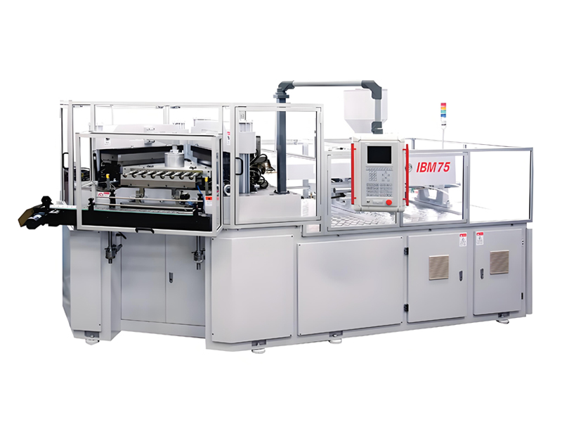
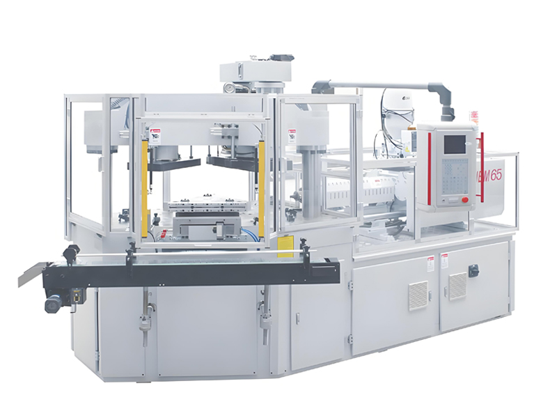
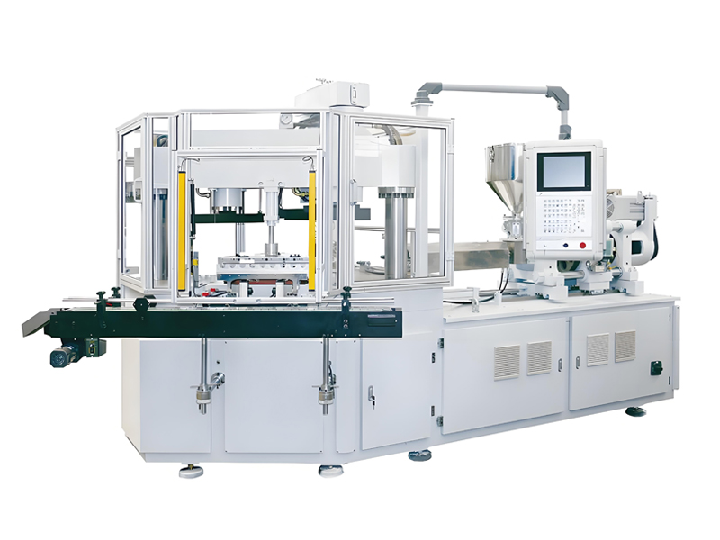
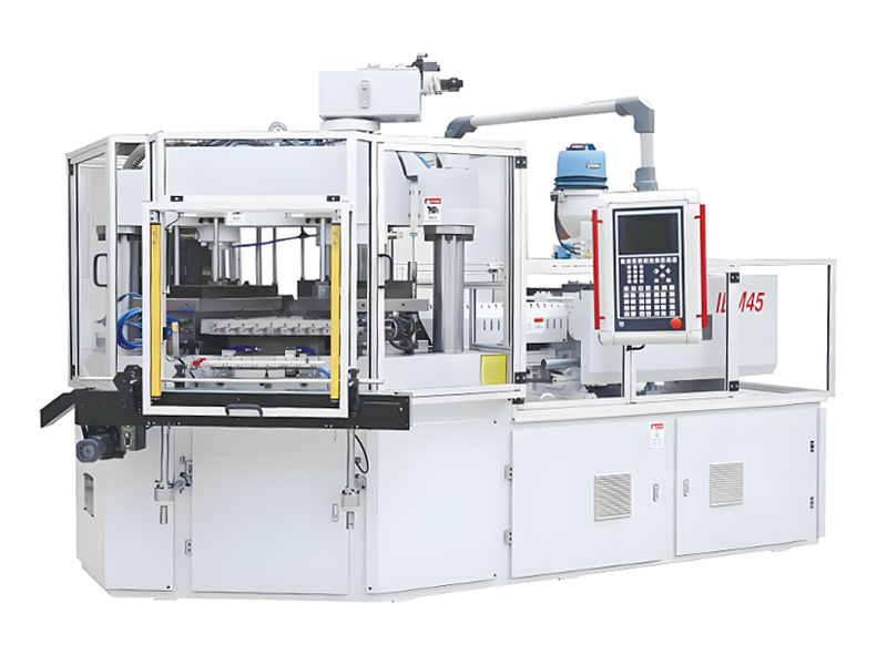
Aibim, a Wanplas factory, has specialized in injection blow molding machines for more than twelve years, with a combined twenty years of experience in the injection blow molding process specifically. The factory operates its own CNC machining center for critical machine components, moved into a new plant in 2022 with an annual capacity of more than 100 machines, and supplies customers in over 40 countries. Its three-station, one-step I(S)BM platform — the IBM75, IBM65 and IBM55 Hybrid Electric — covers containers from 3 ml to 1000 ml in PE, PP, PS, ABS, SAN, PC, PCTG, PETG and TPU. Everything below is framed around how that equipment is actually delivered, installed, proven and handed over.
1. Lo que “llave en mano” incluye y excluye realmente
The single most common source of friction in a turnkey injection blow molding project is an undefined scope boundary. “Turnkey” is a commercial word, not a technical one, and two parties can sign the same contract with completely different mental models of who supplies the compressed air piping or who pays for the crane on unloading day. Before any schedule is drawn, the scope matrix must be agreed line by line and signed as an annex to the contract.
A well-constructed scope matrix separates three categories: included items that are inside the quoted package, optional items the customer may add at order stage, and customer scope items that must be completed locally before the equipment arrives. Ambiguity in the third column is what causes machines to sit crated on a factory floor for six weeks waiting for a power connection.
| Scope item | Status | What it covers | Typical boundary point |
|---|---|---|---|
| Máquina de moldeo por inyección y soplado | Included | Complete three-station machine, clamping unit, injection unit, hydraulic and control system, safety package | Machine terminal block and utility inlet connections |
| Mold set (injection mold, blow mold, neck insert) | Included | Full three-part IBM mold tooling matched to the approved product drawing | Signed first-article sample |
| Dehumidifying dryer | Included | Drying hopper plus dehumidifying unit sized to line throughput | Hopper flange at machine throat |
| Chiller and cooling circuit skid | Included | Chilled water generation for injection and blow mold circuits | Chiller inlet and outlet manifold |
| Mold temperature controller | Included | Closed-loop control of injection mold circuit temperature | Quick couplings at mold face |
| Hopper loader | Included | Vacuum conveying of resin from drum or silo to drying hopper | Suction lance |
| Take-away conveyor | Included | Belt conveyor from stripper station to collection bin | Discharge end |
| Air compressor and air dryer | Optional | Blow air generation, filtration and drying to instrument quality | Compressor outlet valve |
| Leak tester and vision inspection | Optional | Downstream automatic quality gating | Conveyor handover point |
| Installation and commissioning | Included | Engineer time on site for positioning verification, connection checks, process establishment | Signed SAT report |
| Operator and technician training | Included | Structured three-level program delivered on the installed machine | Signed training certificates |
| Documentation package | Included | Operation manual, maintenance manual, electrical and pneumatic diagrams, mold drawings, wear-part list | Handover checklist signature |
| Spare parts kit | Included | Commissioning spares plus USD 500 free parts/year policy | Packing list confirmation |
| Foundation, floor slab and load capacity | Customer scope | Concrete slab thickness, flatness and bearing capacity | Site readiness declaration |
| Electrical supply, transformer, main breaker, cabling | Customer scope | Incoming power up to the machine disconnect | Local electrician certification |
| Cooling water piping, compressed air piping, drains | Customer scope | Distribution from utility room to the cell | Pressure-tested pipe ends |
| Crane, forklift, rigging on arrival | Customer scope | Unloading, moving and positioning of crates | Machine set on its feet |
| Raw material and colorant for trials | Customer scope | Production-grade resin identical to intended mass production | Material certificate provided |
| Customs clearance, import duty, local permits | Customer scope | Port handling, clearance, environmental and safety permits | Delivery to factory gate |
| After-sales technical support | Included | Remote diagnostics, parameter support, warranty handling | Ongoing through warranty period and beyond |
Por qué la columna «alcance del cliente» decide su planificación
Every included item is under the equipment supplier’s schedule control and is therefore predictable. Every customer scope item sits on the critical path but is managed by a different organization, often by a facilities team that has never installed a molding cell. In practice, more than half of all turnkey delays in injection blow molding projects trace back to three customer scope items: electrical capacity, cooling water availability and the readiness of the concrete slab. Aibim addresses this by issuing the utility requirement sheet and the English-language installation drawing package at contract stage, not at shipping stage, so the facilities team has months rather than days to react.
Llave en mano no significa responsabilidad llave en mano del diseño del producto
One boundary deserves explicit mention. The equipment supplier is responsible for the machine achieving its specified dry cycle, shot capacity, repeatability and safety functions, and for the mold producing parts that conform to the approved drawing. The customer remains responsible for the product design itself — wall thickness distribution, neck finish standard, label panel geometry, brand requirements and regulatory compliance of the finished container. A design for manufacturability review is offered as part of the mold development phase precisely so that design decisions with heavy process consequences are challenged early, while changing them still costs almost nothing.
2. Fase 0 — Definición de requisitos y modelado de capacidad
Phase 0 happens before any purchase order and determines almost everything that follows. The task is to work backwards from the end product to the machine: given a container volume, a material, a neck specification and an annual demand figure, how many cavities are required, which model carries them, and what utilities and staffing does that imply? Every hour spent here saves roughly a week later in the project.
Las cinco entradas que definen un proyecto
- Volumen y geometría del envase. El moldeo por inyección-soplado cubre de 3 ml a 1000 ml en la plataforma Aibim. El volumen impulsa el peso de inyección, el tiempo de enfriamiento y el espaciado de cavidades, que a su vez impulsan la fuerza de cierre y el tamaño de la base del molde.
- Material. PP, HDPE, LDPE, LLDPE, PS, ABS, SAN, PC, PCTG, PETG and TPU each behave differently in the injection stage and in the blow stage. Semi-crystalline resins such as PP and HDPE need longer cooling and shrink more; amorphous resins such as PS, SAN and PETG hold dimensions more tightly but are more sensitive to residual stress and require careful drying.
- Acabado de cuello y sistema de cierre. El cuello se moldea por inyección a dimensiones finales en un proceso IBM, por lo que el perfil de la rosca, la superficie de sellado y el anillo de inviolabilidad deben especificarse contra un estándar definido antes de cortar el acero.
- Demanda anual y patrón de turnos. La cantidad anual dividida por las horas de funcionamiento anuales planificadas da la producción horaria requerida, que es el ancla de todo el modelo de capacidad.
- Régimen de calidad. Los envases farmacéuticos, los envases de contacto alimentario y los envases químicos industriales imponen diferentes requisitos de inspección, documentación y limpieza, que afectan la configuración de la línea e incluso la disposición física de la celda.
La fórmula de capacidad
El modelo de capacidad de trabajo para una celda de moldeo por inyección-soplado es deliberadamente simple, porque un modelo simple que todos entienden supera a un modelo complejo que nadie audita:
Annual output = hourly output × planned running hours per year
Required cavities = (annual demand ÷ planned running hours) ÷ ((3600 ÷ cycle time) × OEE)
Three cautions apply. First, cycle time in the formula is the production cycle with the real resin and the real wall thickness, not the machine’s dry cycle. Dry cycle is a machine capability figure measured without melt; production cycle is dominated by the injection mold cooling of the parison and is typically two to four times longer. Second, OEE must be realistic and phase-dependent — a line that will eventually run at 85 percent OEE will not do so in week two. Third, always model at least a 15 percent headroom against nominal demand, because demand forecasts in packaging are revised upward far more often than downward.
| Product type | Volume | Typical material | Wall thickness | Typical cycle time (s) | Typical cavities | Hourly output at 85% OEE (pcs/h) |
|---|---|---|---|---|---|---|
| Pharmaceutical dropper vial | 3–15 ml | PE / PP | 0.6–0.9 mm | 9–12 | 16–24 | 4,100–8,200 |
| Oral liquid bottle | 20–60 ml | PP / PS | 0.8–1.1 mm | 11–14 | 12–20 | 2,600–5,600 |
| Cosmetic serum bottle | 30–60 ml | PETG / PCTG / SAN | 1.0–1.6 mm | 14–18 | 8–12 | 1,400–2,600 |
| Cream jar | 50–150 ml | PP / SAN | 1.2–2.0 mm | 16–22 | 6–10 | 980–2,000 |
| Probiotic or dairy shot bottle | 80–150 ml | PS / PP | 0.7–1.0 mm | 12–16 | 10–16 | 1,900–4,000 |
| Condiment or sauce bottle | 200–500 ml | PP / HDPE | 1.0–1.5 mm | 18–26 | 6–10 | 700–1,600 |
| Household chemical bottle | 500–1000 ml | HDPE / PP | 1.2–1.8 mm | 24–34 | 4–8 | 360–1,000 |
| Reagent or laboratory bottle | 100–500 ml | PP / PC | 1.4–2.2 mm | 20–30 | 4–8 | 410–1,200 |
Leer correctamente el modelo de capacidad
Suppose the requirement is 40 million 10 ml pharmaceutical vials per year, running two shifts, 300 days, with 15 hours of planned running per day — 4,500 running hours. Required hourly output is approximately 8,900 pieces. At a 10 second cycle and 85 percent OEE, one cavity yields 306 pieces per hour, so roughly 29 cavities are needed. That immediately signals a high-cavitation configuration on the largest platform, or two smaller machines running in parallel. The parallel option costs more in capital but removes single-point failure risk and allows one machine to run a second product family — a trade-off that should be settled in Phase 0, not discovered in month eight.
The same arithmetic run in reverse is what protects a project from the most damaging mistake in packaging capital planning: ordering a machine sized to today’s order book, then discovering that the mold cannot be re-cavitated because the platen and tie-bar spacing were never sized for it. Specifying one platform size above the immediate need is almost always cheaper than buying a second machine eighteen months later.
3. Por qué el moldeo por inyección y soplado en lugar de la extrusión y soplado o el proceso de dos etapas
Choosing the process route is a Phase 0 decision with permanent consequences, because the mold investment, the scrap economics and the achievable neck tolerance are all locked in by it. Three routes compete for small and medium rigid containers: one-step injection blow molding, extrusion blow molding, and two-step injection stretch blow molding using stored preforms.
Injection blow molding produces the neck and the parison by injection into a steel cavity, then transfers the still-hot parison on a core rod to a blow station where it is inflated against the blow mold, and finally strips the finished container at a third station. Because the parison is injection molded rather than extruded, there is no pinch-off, no flash, no tail and no trimming operation. The neck is formed to injection-molding tolerances rather than blow-molding tolerances, which is decisive for pharmaceutical closures, child-resistant caps, dropper inserts and pump fitments.
| Criterion | Injection blow molding (one-step IBM) | Extrusion blow molding (EBM) | Two-step injection stretch blow molding |
|---|---|---|---|
| Precisión del cuello | Injection-grade, typically ±0.05–0.10 mm on thread and sealing surface | Blow-grade, calibrated neck typically ±0.15–0.30 mm | Injection-grade on preform neck, carried into the bottle |
| Flash and trimming | None — no pinch-off, no deflashing station required | Pinch-off flash at base and neck; trimming and regrind loop required | None on the blowing step |
| Process scrap rate at steady state | Typically 0.5–2% | Typically 8–20% recirculated as regrind | Typically 1–3% plus preform handling losses |
| Mold cost level | High — three coordinated tool sets required | Low to Medium — single blow mold set | Premium at high cavitation, Medium for small runs |
| Suitable volume range | 3–1000 ml | 50 ml to several hundred liters | 200 ml to 20 L, dominated by beverage sizes |
| Handle-ware capability | Not possible — no pinch-off to form a handle | Yes, integral handles are a core strength | Only with separate handle attachment |
| Base and shoulder wall control | Excellent — parison thickness profile defined by steel | Good with parison programming, but variable | Excellent through biaxial orientation |
| Eficiencia de material | Very high — near net shape, weight repeatability typically within ±1.5% | Moderate — regrind loop degrades material over cycles | High, but requires preform inventory and reheating energy |
| Cosmetic clarity | Excellent with PS, SAN, PETG, PCTG | Moderate; parting line visible on body | Excellent with PET |
| Inventory model | Single-stage, no intermediate stock | Single-stage | Two-stage — preform stock buffer required |
| Changeover complexity | Medium — three tool sets change together | Low to Medium | Low on blower, but preform tooling change is heavy |
| Typical industries | Pharmaceutical, cosmetics, oral care, diagnostics, specialty food | Household chemicals, lubricants, agrochemicals, large containers | Water, carbonated beverages, edible oil, high-volume commodity |
| Best fit | Small to medium containers where neck precision and zero flash matter | Large containers, handled containers, cost-driven commodity | Very high volume single-SKU beverage production |
La regla de decisión en un párrafo
If the container is under one liter, the neck must seal against a pump, dropper, child-resistant closure or induction liner, and the customer is unwilling to accept trimming marks or a body parting line, injection blow molding wins on total cost of ownership even though its tooling cost level is higher. If the container needs an integral handle or exceeds a few liters, extrusion blow molding is the only practical route. If the product is a commodity beverage in PET at extremely high volume with a single SKU, two-step injection stretch blow molding wins on throughput per operator. Most pharmaceutical and cosmetics projects that end up on an Aibim line arrive there because the neck tolerance and the zero-flash requirement eliminated the alternatives before cost was even discussed.
Dónde la economía del desperdicio domina silenciosamente
A frequently underestimated factor is what happens to the regrind loop over a product’s life. In extrusion blow molding, 8 to 20 percent of throughput becomes flash that is granulated and reintroduced. Every pass through the extruder shortens polymer chains, and for regulated packaging the permitted regrind fraction is often capped or prohibited entirely — meaning the flash becomes waste rather than recirculated material. Over a multi-year program producing tens of millions of units, the difference between a 1 percent scrap process and a 12 percent unusable-flash process compounds into a material consumption gap that no tooling saving can offset. This is the argument that most often converts a project from extrusion blow to injection blow.
4. Fase 1 — Contrato, congelación de especificaciones y artículos de plazo largo
Phase 1 converts an agreed technical concept into a frozen, buildable specification and releases the long-lead items. The governing rule is that the specification freeze date is the true start of the project schedule, not the contract date. A contract signed in week 0 with an open specification produces a project that genuinely starts in week 5, and no amount of expediting later recovers those five weeks.
La lista de verificación de congelación de especificaciones
Congelar una especificación significa que cada parámetro siguiente tiene un valor único, escrito y mutuamente confirmado. Cualquier cosa dejada como “por confirmar” se convierte en una orden de cambio, y las órdenes de cambio en el dominio del molde o eléctrico son la categoría más cara de daño al cronograma en todo el proyecto.
- Suministro eléctrico: voltaje, número de fases, frecuencia, disposición de neutro y puesta a tierra, tamaño del cable de entrada y capacidad de cortocircuito. Una máquina construida para 380 V / 50 Hz no puede reconectarse en sitio a 480 V / 60 Hz sin cambios de transformador y control.
- Safety and conformity standard: the target market determines the safety package. CE conformity is standard on the Aibim platform, including a light curtain for personal safety and a long-distance digital laser sensor at the stripper station for mold protection. Other destination markets may require additional documentation or marking.
- Idioma y unidades de control: idioma de la HMI, unidades de visualización métricas o imperiales, formatos de fecha y número, niveles de acceso de operadores y política de contraseñas.
- Color y marcado de la máquina: esquema de color estándar a menos que se especifique un color corporativo por escrito en la etapa de pedido; los cambios de color tardíos fuerzan el retrabajo de los ensambles pintados.
- Interfaces: contactos secos o señales de bus de campo para transportadores posteriores, probadores de fugas, robots y recolección de datos de planta; asignaciones de relés de alarma; cualquier protocolo de salida de datos requerido.
- Paquete de producto: modelo 3D final y dibujo 2D del envase, estándar de acabado del cuello, peso objetivo y tolerancia de peso, mapa de espesor de pared, grado de material y colorante, y muestra del cierre.
- Cavitación y configuración del molde: número de cavidades, material de la varilla de núcleo, intención del diseño del circuito de enfriamiento, decisión de canal caliente o canal frío, y si se permite el utillaje familiar.
- Base de dimensionamiento auxiliar: el rendimiento confirmado se usa para dimensionar el secador, el enfriador y el compresor, incluyendo cualquier segunda familia de productos planificada.
- Envío y documentación: incoterm, puerto de destino, tipo de contenedor, estándar de embalaje y la lista de documentos requeridos para el despacho aduanero.
Artículos de plazo largo y por qué definen la ruta crítica
Once frozen, the specification releases procurement. Some items can be pulled from stock and installed in days; others carry lead times measured in months and therefore sit on the critical path from day one. The discipline is to identify these on the day of contract and to place them immediately rather than waiting for the rest of the design package to mature.
| Milestone or item | Typical lead time from specification freeze | Sits on critical path? | Owner | Consequence if late |
|---|---|---|---|---|
| Product 3D model and drawing approval | 0 (must exist at freeze) | Yes | Customer | Entire mold chain shifts one-for-one |
| Design for manufacturability review and sign-off | 5–10 days | Yes | Joint | Steel cut against an unbuildable design |
| Mold flow simulation report | 5–8 days | Sometimes | Supplier | Gate and cooling issues discovered at T0 instead of on screen |
| Mold steel procurement and pre-hardening | 10–20 days | Yes | Supplier | Machining queue idles |
| Complete IBM mold set (three coordinated tools) | 45–70 days | Yes | Supplier | No trial possible, FAT cannot be scheduled |
| Machine base casting and frame machining | 20–30 days | Yes | Supplier | Assembly start delayed |
| Servo drives and motion components | 25–45 days | Yes on hybrid electric configurations | Supplier | Hybrid electric build cannot be completed |
| Hydraulic variable displacement pump package | 20–35 days | Yes | Supplier | Power unit assembly blocked |
| Control cabinet build and wiring | 15–25 days | Partially | Supplier | Machine cannot be powered for testing |
| Non-standard clamping or extended daylight configuration | Add 15–25 days | Yes | Supplier | Special build slips the whole assembly slot |
| Dehumidifying dryer, chiller, loader, conveyor | 15–30 days | No | Supplier | Usually absorbed by schedule float |
| Air compressor and air treatment | 15–30 days | No, unless customer scope | Joint | Blow air unavailable at commissioning |
| Customer transformer upgrade or new feeder | 30–90 days | Yes | Customer | Machine idle on the floor after arrival |
| Floor slab reinforcement or repair | 15–45 days | Yes | Customer | Positioning and leveling cannot proceed |
| Sea freight transit | 18–45 days depending on route | Yes | Joint | Direct calendar shift to installation |
| Customs clearance and inland transport | 3–15 days | Yes | Customer | Demurrage exposure and installation team rescheduling |
La disciplina de las órdenes de cambio
After freeze, changes are not forbidden — they are priced in time before they are priced in anything else. A useful contractual mechanism is a two-column change note: every proposed change must state its schedule impact in days and its acceptance impact in terms of which already-passed gate must be re-run. A neck diameter change of 0.5 mm after steel is cut is not a small change; it invalidates the injection mold cavity, the neck insert and potentially the core rod set, and it re-opens the mold flow analysis. Making that visible on one page stops most late changes without any argument.
Quién es responsable de la Fase 1
Phase 1 needs a single named project owner on each side, with authority to approve technical decisions without escalating. Projects run by committee lose an average of one to two weeks per gate simply in circulation time. The most successful turnkey injection blow molding projects assign one customer-side engineer who owns the product drawing, the utility readiness and the sample approval, and one supplier-side project engineer who owns the machine build, the mold schedule and the acceptance documentation. Those two people should speak weekly from contract signature to the end of ramp-up.
5. Fase 2 — Cronograma de desarrollo del molde
Mold development is the longest single activity in a turnkey injection blow molding project and therefore deserves the most granular planning. An injection blow molding tool is not one mold — it is three coordinated tool sets that must share a common index geometry: the injection mold that forms the parison and the finished neck, the blow mold that forms the container body, and the neck insert set together with the core rods that carry the parison from station to station. All three must be machined to a common datum, because the transfer between stations is mechanical and unforgiving.
Por qué tres juegos de herramientas cambian las matemáticas del programa
In a conventional injection molding project, one tool moves through the shop and one trial validates it. In injection blow molding, three tools move through the shop in parallel and must converge on a single trial date. If the blow mold finishes two weeks before the injection mold, nothing can be tested; if the neck insert set has a hardness or fit deviation, both other tools wait. The practical consequence is that the mold schedule must be managed as a convergent network, with the neck insert treated as the pacing item because it is the smallest, most precise and most easily underestimated component of the set.
Aibim manufactures the machine and the matching mold series in-house, using its own CNC machining center for critical components. That matters less as a marketing point than as a schedule mechanism: when the tool designer and the machine designer sit in the same building, the index tolerance, the core rod length, the stripper stroke and the clamp daylight are reconciled on a single drawing set rather than negotiated between two organizations after steel is cut.
| Stage | Duration (days) | Deliverable | Customer confirmation point |
|---|---|---|---|
| Product 3D model receipt and feasibility screening | 2–3 | Feasibility statement, volume and weight verification | Confirm the model is the final revision |
| Design for manufacturability review | 3–5 | DFM report covering draft angles, wall thickness map, neck geometry, parting line, gate location and stripper clearance | Written approval of every proposed geometry change |
| Mold flow simulation | 4–6 | Fill pattern, pressure drop, cooling profile, predicted parison temperature at transfer, warpage indication | Approve gate position and cavity balance |
| Mold 3D design and 2D detailing | 7–12 | Complete assembly model of injection mold, blow mold, neck insert and core rod set with cooling circuit design | Sign the mold design drawing set |
| Steel procurement and pre-machining | 8–14 | Certified steel blanks, rough-cut plates and inserts | Approve steel grade and hardness specification |
| CNC rough machining of plates and inserts | 7–12 | Rough cavities, cores, plate pockets, cooling line drilling | None — internal gate |
| Tratamiento térmico y alivio de tensiones | 4–7 | Hardness report per component | None — internal gate |
| Precision machining, electrode production and electrical discharge machining | 10–16 | Finished cavity surfaces, neck thread detail, core rod sealing surfaces | None — internal gate |
| Polishing, texturing and surface finishing | 3–6 | Specified surface finish on cavity and blow mold | Approve surface finish sample if cosmetic |
| Mold assembly and fitting | 4–7 | Assembled three-part tool set, cooling circuit pressure test, mechanical fit check | None — internal gate |
| T0 first trial on the production machine | 1–2 | First shots, dimensional measurement report, photographs of parts | Review T0 report and issue correction list |
| T1 correction and retrial | 5–10 | Corrected tool, second trial report, weight and wall thickness data | Review T1 report |
| T2 fine tuning and validation | 4–8 | Dimensional capability check, leak and drop test results, cosmetic assessment | Confirm remaining items or approve |
| Sample dispatch and final sample approval | 5–12 including courier transit | Signed first-article sample set with measurement records | Written sample approval — the gate that releases FAT |
Leer el cronograma del molde con honestidad
Summing the durations gives a range of roughly 45 to 70 working days for a straightforward single-family tool set, and this assumes prompt customer response at every gate. The most common cause of overrun is not machining capacity but response latency: a DFM report that waits nine days for an answer adds nine days to the delivery date, one for one. The second most common cause is a product revision arriving after steel procurement. A practical countermeasure is to agree a maximum response window — typically 48 hours for routine confirmations and five working days for sample approval — and to write it into the contract as a mutual obligation rather than a supplier-only obligation.
Qué prueban realmente T0, T1 y T2
T0 answers a binary question: does the tool set index, close, fill, transfer, blow and strip without collision? Cosmetics and dimensions are secondary at T0. T1 addresses dimensional conformity — weight, neck thread go and no-go gauging, height, diameter, ovality and wall thickness distribution. T2 addresses process robustness: can the tool run at target cycle across a realistic parameter window without short shots, flash at the neck, transfer marks or stripper damage? Only after T2 does a sample set genuinely represent what mass production will look like. Approving samples that came from a heroic, hand-tuned T0 shot is one of the classic ways a project passes every gate and still fails in month three.
Decisiones de diseño con el mayor apalancamiento en el programa
- Estándar de acabado de cuello. Seleccionar un estándar de cuello reconocido y dimensionado en lugar de una rosca a medida elimina la ambigüedad de medición y permite producir calibres pasa y no pasa en paralelo con la herramienta.
- Uniformidad del espesor de pared. Un párison cuya pared varía más de aproximadamente un 25 por ciento a lo largo de su longitud fuerza un enfriamiento comprometido y alarga el ciclo. Corregir esto en la etapa DFM cuesta una revisión de plano; corregirlo en T1 cuesta un inserto de cavidad.
- Geometría de la base. Las bases de empuje profundas y los radios de base afilados concentran el estrés y ralentizan el enfriamiento. Suavizarlos temprano compra tiempo de ciclo para toda la vida del programa.
- Panel de etiqueta y profundidad de grabado. El grabado profundo en el molde de soplado atrapa aire y produce detalles sin rellenar. La ubicación de las ventilaciones debe diseñarse, no descubrirse.
- Simetría del número de cavidades. Los números pares de cavidades con balance simétrico de canales son mucho más fáciles de llevar a la tolerancia de peso que las disposiciones impares o asimétricas.
6. Serie de máquinas IBM de Aibim
Aibim builds a three-station, one-step injection blow molding platform in three frame sizes, covering containers from 3 ml to 1000 ml. All three share the same architectural principles: a single-crossbeam, double-pole clamping framework that enlarges the usable mold setting space; PREFILL technology combined with variable displacement pump pressurizing in the hydraulic system, delivering a minimum 35 percent reduction in energy consumption compared with conventional fixed-displacement hydraulic machines; an SD card parameter storage system that allows a validated process to be copied between machines; and a CE-compliant safety package with a light curtain for personnel protection and a long-distance digital laser sensor at the stripper station for mold protection.
| Parameter | IBM55 Hybrid Electric | IBM65 | IBM75 |
|---|---|---|---|
| Clamping force (kN) | 550 | 650 | 750 |
| Injection capacity (g, PS equivalent) | 120 | 190 | 270 |
| Screw diameter (mm) | 35 | 40 | 45 |
| Screw L/D ratio | 22:1 | 22:1 | 22:1 |
| Maximum product volume (ml) | 300 | 500 | 1000 |
| Minimum product volume (ml) | 3 | 3 | 5 |
| Number of stations | 3 — injection, blow, stripper | 3 — injection, blow, stripper | 3 — injection, blow, stripper |
| Cavity range | 4–12 | 4–16 | 6–24 |
| Dry cycle (s) | 4.5 | 5.0 | 5.5 |
| Drive concept | Hybrid electric, servo-driven plasticizing with hydraulic clamping | Hydraulic with variable displacement pump and PREFILL | Hydraulic with variable displacement pump and PREFILL |
| Installed power (kW) | 45 | 60 | 75 |
| Typical operating power draw (kW) | 18–26 | 26–36 | 32–46 |
| Machine dimensions L×W×H (mm) | 4600 × 1800 × 2300 | 5200 × 2000 × 2500 | 5800 × 2200 × 2600 |
| Machine weight (t) | 7.5 | 10.0 | 13.0 |
| Processable materials | PE, PP, PS, ABS, SAN, PETG, PCTG, TPU | PE, PP, PS, ABS, SAN, PC, PETG, PCTG, TPU | PE, PP, PS, ABS, SAN, PC, PETG, PCTG, TPU |
| Sistema de control | PLC with color touch screen HMI, SD card recipe transfer | PLC with color touch screen HMI, SD card recipe transfer | PLC with color touch screen HMI, SD card recipe transfer |
| Safety package | CE — light curtain, laser mold protection, interlocked guards | CE — light curtain, laser mold protection, interlocked guards | CE — light curtain, laser mold protection, interlocked guards |
Las cifras anteriores son configuraciones representativas para la planificación de proyectos. Los valores finales, incluidos el número de cavidades, la especificación del husillo y la carga conectada, se confirman en la hoja de especificaciones del pedido frente al dibujo del producto aprobado.
Cómo interpretar los tres modelos frente a un proyecto
IBM55 Hybrid Electric is the choice when energy cost per thousand containers is the dominant operating metric, when the product family sits below 300 ml, and when the project needs the tightest shot repeatability for small pharmaceutical or diagnostic containers. The servo-driven plasticizing unit removes the idle hydraulic losses that dominate energy consumption on small machines running short cycles, and the reduced heat rejection lowers the chiller duty as well — a second-order saving that project engineers routinely forget to count.
IBM65 is the general-purpose workhorse. Its 500 ml ceiling and 4 to 16 cavity range cover the overwhelming majority of cosmetics, oral care and mid-size food containers, and its mold setting space accommodates the tool widths that most 100 ml to 300 ml families require. When a customer’s product roadmap is uncertain, IBM65 is the configuration least likely to become a constraint within three years.
IBM75 is specified when the project needs either the largest container volume on the platform, up to 1000 ml, or the highest cavitation for small containers, up to 24 cavities. These are two different reasons to buy the same machine, and they lead to very different mold and auxiliary configurations. A 24-cavity 10 ml pharmaceutical tool on an IBM75 is a high-output, short-cycle, high-cooling-duty application; a 6-cavity 1000 ml household chemical tool on the same frame is a long-cycle, high-shot-weight application. The machine is identical; the dryer, chiller and compressor sizing are not.
Características de la plataforma que importan durante la puesta en marcha
- PREFILL and variable displacement pumping. During clamping and mold traverse, PREFILL circuits move large oil volumes at low pressure while the variable displacement pump delivers only the flow the movement actually needs. The measurable outcome is at least 35 percent lower energy consumption than a comparable fixed-displacement hydraulic machine, plus a cooler oil tank, which improves parameter stability across a full shift.
- SD card recipe portability. A validated parameter set can be exported and loaded onto a second machine of the same model. For multi-machine projects and for regulated products transferred between sites, this compresses the second machine’s commissioning from days to hours and makes the process transfer auditable.
- Sujeción de viga transversal única y doble poste. El espacio ampliado para el montaje de moldes es lo que permite adaptar posteriormente un mayor número de cavidades en el mismo marco: la pieza de preparación para el futuro más valiosa de toda la decisión de capital.
- Monitoreo del extractor con láser. El sensor láser digital de larga distancia en la estación de extracción detecta un contenedor que no se ha liberado antes de que la pinza se cierre sobre él. En un turno nocturno sin supervisión, esto es la diferencia entre una pieza de desperdicio y una cavidad dañada.
- Indexación de tres estaciones. Debido a que la inyección, el soplado y el desmoldeo ocurren simultáneamente en tres posiciones, el ciclo de la máquina está gobernado por la estación más lenta en lugar de la suma de las tres. Por lo tanto, optimizar el enfriamiento de la estación de inyección tiene un efecto directo y medible en la producción total.
7. Paquete de equipos auxiliares
An injection blow molding machine without correctly sized auxiliaries is a machine that will never reach its rated cycle. In practice, most cycle-time shortfalls discovered during ramp-up are not machine problems at all — they are cooling capacity shortfalls, unstable chilled water temperature, insufficient blow air flow, or resin that was not dried to specification. The auxiliary package therefore deserves the same engineering rigor as the machine itself, and it must be sized against the peak demand of the intended tool, not the average.
| Equipment | Sizing basis | Typical capacity for one IBM75 line | Power (kW) | Critical specification |
|---|---|---|---|---|
| Dehumidifying dryer with drying hopper | Throughput in kg/h multiplied by required residence time in hours, plus 25 percent margin | 75 kg/h airflow-matched unit with 150–200 L hopper | 9–15 | Dew point of minus 40 °C or lower measured at the hopper inlet; independent temperature control per hopper |
| Water chiller | Melt cooling heat load, approximately 0.25–0.35 kW of cooling per kg/h of throughput, plus hydraulic oil cooling | 18–25 kW cooling capacity, water-cooled or air-cooled | 7–10 | Chilled water at 8–12 °C with stability of ±1 °C; separate circuits for blow mold and hydraulic cooling |
| Mold temperature controller | One controller per independently controlled circuit | Two units of 9–12 kW heating capacity for the injection mold circuits | 9–12 each | Control accuracy of ±1 °C; injection mold circuit typically 15–40 °C depending on resin |
| Air compressor | Blow air volume per cycle multiplied by cycles per hour, plus pneumatic actuation and 30 percent reserve | 1.5–2.2 m³/min free air delivery at 1.0–1.2 MPa | 11–18.5 | Oil-free or class-filtered supply for food and pharmaceutical contact; receiver tank sized to absorb blow peaks |
| Refrigerated air dryer and filtration train | Matched to compressor free air delivery | 2.5 m³/min refrigerated dryer with three-stage filtration | 0.8–1.5 | Pressure dew point of plus 3 °C or lower; oil carry-over below 0.01 mg/m³ for regulated products |
| Hopper loader | Two to three times the line consumption rate for intermittent duty | 300–600 kg/h vacuum loader | 0.75–1.5 | Level sensing with alarm; stainless contact parts for pharmaceutical resins |
| Take-away conveyor | Machine discharge height and distance to the collection point | 3–6 m belt conveyor with adjustable speed | 0.4–0.75 | Anti-static belt and smooth transitions to avoid scuffing on transparent containers |
| Leak tester | Line output rate at target OEE | 1,200–3,600 containers per hour, inline or offline | 0.5–1.5 | Test pressure typically 20–40 kPa with automatic reject and counting |
| Cooling tower for water-cooled chillers | Chiller heat rejection plus 20 percent | 30–40 kW rejection duty | 1.5–3.0 | Water treatment and filtration to prevent scaling in mold circuits |
| Granulator for startup purge and rejects | Purge mass per startup and changeover | Beside-the-press unit, 20–50 kg/h | 3–5.5 | Sound-insulated; sealed collection for regulated production areas |
Los tres errores auxiliares que más tiempo cuestan
Undersized chilled water. A chiller specified against average heat load will hold temperature during a two-hour trial and lose it during a twelve-hour production shift, at which point cycle time creeps upward and wall thickness drifts. Chilled water stability of ±1 °C is not a luxury on transparent containers — it is the difference between consistent clarity and visible batch-to-batch variation. Size the chiller against the highest-cavitation, shortest-cycle tool the machine will ever run, not the tool being commissioned first.
Blow air that collapses under peak demand. Blow air is consumed in short, high-flow bursts. A compressor sized on average consumption will show acceptable numbers on paper and then sag below the required 0.6 to 1.0 MPa at the instant of blowing, producing under-formed shoulders and inconsistent internal volume. A correctly sized receiver tank close to the machine solves most of this, and it costs a fraction of a larger compressor.
Drying treated as a formality. Hygroscopic resins processed wet degrade in the barrel, producing splay, reduced impact strength and, in transparent containers, visible haze. Verify dew point at the hopper inlet with an instrument rather than trusting the panel display, and confirm that residence time at temperature actually matches the resin requirement at the running throughput — a hopper sized for 40 kg/h delivers only half the intended residence time when the line runs at 80 kg/h.
Dimensionamiento de los auxiliares para la segunda familia de productos
Almost every packaging producer adds a second and third product family within two years of installing a line. The marginal cost of specifying a chiller one size larger and a compressor with 30 percent reserve at order stage is modest; the cost of replacing them later includes not only the equipment but the shutdown, the re-piping and the re-validation. When the capacity model in Phase 0 identifies a plausible future product, size the utility-facing auxiliaries — chiller, compressor, dryer — against that future product and size the product-facing auxiliaries — conveyor, leak tester — against today’s.
8. Fase 3: Preparación del sitio y servicios públicos
Site preparation is the phase most often started too late, because it belongs to the customer’s facilities organization rather than to the project team that signed the contract. The rule that prevents most problems is simple: site preparation must be finished and formally declared complete before the equipment leaves the port of origin, not before it arrives at the factory gate.
Aibim supplies English-language installation and connection drawings showing machine footprint, service connection positions, access clearances and utility entry points, so the customer’s facilities team and local contractors can work from a single reference document. Detailed floor-plan design for a complete bottle plant is a separate engineering exercise with its own methodology and is treated in its own dedicated discussion; this phase is concerned only with confirming that the site can physically and electrically accept the equipment on the agreed date.
| Utility or site item | Requirement for one IBM75 line | Customer responsibility |
|---|---|---|
| Floor slab | Reinforced concrete, minimum 150 mm thickness, bearing capacity of at least 5 t/m², flatness within 5 mm over 2 m | Slab construction, repair, surface preparation and verification before arrival |
| Electrical supply | Three-phase supply matched to the frozen specification; machine installed load 75 kW plus auxiliaries, giving a typical cell demand of 110–140 kW with diversity applied | Transformer capacity, main breaker, feeder cable, local disconnect, earthing and certification by a licensed electrician |
| Earthing and power quality | Dedicated protective earth with resistance below 4 Ω; voltage fluctuation within ±10 percent; harmonic mitigation where the plant carries heavy inverter load | Installation and a written measurement report |
| Cooling water | Chilled water at 8–12 °C, flow of 60–90 L/min at 0.3–0.4 MPa to the cell manifold, with a separate return line | Piping from the utility room, insulation, valves, filters, pressure gauges and drains |
| Aire comprimido | 1.5–2.2 m³/min free air delivery at 1.0–1.2 MPa at the machine inlet, dried and filtered | Compressor room, distribution piping sized to avoid pressure drop, receiver tank near the cell |
| Overhead lifting | Crane or gantry with capacity of at least 3 t over the mold area for tool changes, with hook height clear of the 2600 mm machine height | Crane installation, load certification and operator licensing |
| Access route and door opening | Clear opening of at least 2.6 m width and 2.8 m height, with an unobstructed route from the unloading point to the installation position | Door modification, route clearance and floor protection |
| Ambient conditions | Ambient temperature 5–40 °C, relative humidity below 80 percent non-condensing, dust-controlled environment for transparent containers | Ventilation, air conditioning and dust control appropriate to the product class |
| Drainage and containment | Floor drain near the chiller and cooling manifold; oil-spill containment near the hydraulic power unit | Drain installation and containment provision |
| Lighting and safety perimeter | Minimum 300 lux at the operating position, marked safety perimeter and unobstructed emergency egress | Lighting installation, floor marking and safety signage |
La declaración de preparación del sitio
The deliverable that closes this phase is a signed site readiness declaration accompanied by photographs of the installation position, the electrical connection point, the cooling water and compressed air terminations and the access route. It is a five-minute document that eliminates the most expensive failure mode in the entire project — an installation engineer arriving at a site where the machine cannot yet be energized. When the declaration cannot be signed, the installation visit is rescheduled rather than attempted, and both parties save a week.
9. Fase 4 — Prueba de aceptación en fábrica
The factory acceptance test is the gate that converts a built machine into an accepted machine. Its purpose is to prove, at the manufacturing site and before packing, that the equipment meets every specified performance and safety criterion with the customer’s own mold and the customer’s own resin. A FAT run with a generic house mold and a house resin proves the machine works; it does not prove the project works. Insisting on the customer’s tool and material at FAT is the single highest-value decision available to a project manager.
Qué cubre una FAT completa
A FAT for an injection blow molding cell has five parts: a static inspection against the specification, a dry running test without melt, a production trial with the mold installed, a metrology and quality assessment of the parts produced, and a functional test of every safety device. Each part has a written pass criterion agreed before the test date, and each produces a record that becomes part of the handover documentation.
| FAT item | Acceptance criterion | Record method |
|---|---|---|
| Documentation and nameplate check | Model, serial number, voltage, frequency, installed power and conformity marking match the order specification exactly | Photographs plus signed checklist |
| Visual and mechanical inspection | No damage, no oil leakage, all guards fitted, all fasteners torqued, paint finish acceptable | Signed inspection sheet with defect list |
| Dry running test without mold | 8–24 hours of continuous cycling with no alarm, no hydraulic leakage, oil temperature stable within the specified band | Continuous run log with hourly readings |
| Dry cycle verification | Measured dry cycle within 5 percent of the specified value for the model | Stopwatch and controller cycle counter, three repeated measurements |
| Mold installation and index alignment | Three-station index repeatability within tolerance, core rods enter neck inserts without contact marks | Alignment record and photographs |
| Production trial with the customer mold | 4–8 hours of continuous production at target cycle using the customer resin | Process parameter printout and run log |
| Continuous shot count | 500–1000 consecutive cycles without unplanned stoppage attributable to the machine | Controller counter reading before and after, with stoppage log |
| Dimensional sampling | Sample plan agreed in advance; height, neck diameter, thread gauging, weight and wall thickness within the drawing tolerance | Measurement report with instrument identification |
| Weight repeatability | Shot-to-shot weight variation within ±1.5 percent across the sampled cycles | Balance readings tabulated by cavity |
| Cavity-to-cavity balance | Weight spread between cavities within the agreed limit, typically 2–3 percent | Per-cavity weight table |
| Cosmetic assessment | No splay, burn marks, weld line defects, transfer marks, stripper scuffing or unacceptable haze against the agreed boundary samples | Signed visual standard with retained samples |
| Leak and functional testing | Agreed sample quantity passes leak test at specified pressure; closure fit verified with the actual closure | Test report and retained samples |
| Energy consumption measurement | Measured consumption per kilogram processed, or per thousand containers, recorded under stable running conditions | Power analyzer reading with test conditions stated |
| Safety function test | Light curtain stops motion in every guard state; laser stripper sensor triggers correctly; emergency stops, interlocks and safety relays all verified | Safety test checklist, signed by both parties |
| Auxiliary integration test | Dryer, chiller, loader, mold temperature controller and conveyor operate together with the machine without interference or alarm | Integrated run log |
| Spare parts and packing verification | Spare parts kit contents match the packing list; packing standard confirmed before crating | Photographed packing list |
FAT remoto como alternativa práctica
Travel is not always possible, and a remote FAT conducted over live video is now a routine option rather than a compromise. A well-run remote FAT requires three things: a written agenda issued in advance so the customer knows exactly what will be shown and in what order; a camera operator who follows an instruction script rather than wandering; and close-up capture of every instrument reading, controller screen and measurement so the numbers are legible in the recording. Samples produced during the remote FAT are couriered to the customer for independent verification, and final acceptance is issued after those samples are measured locally. In practice, the combination of a live remote session plus independent sample verification produces a stronger evidence trail than a rushed in-person visit.
La lista de pendientes del FAT
No FAT should end with a binary pass or fail. It should end with a punch list of open items, each classified as blocking or non-blocking. Blocking items must be closed before shipment. Non-blocking items — a label in the wrong language, a missing manual annex, a cosmetic paint touch-up — are recorded with an owner and a closure date and follow the machine. This distinction prevents two opposite failure modes: shipping a machine with a real defect, and holding a ready machine in the factory over a trivial item.
10. Fase 5: Envío, instalación y SAT
Shipping and installation is the phase where a well-managed project looks boring and a badly managed one becomes dramatic. The objective is that the machine arrives undamaged, is positioned and leveled correctly the first time, and is connected by people who understood the drawings before the crate was opened.
Planificación del embalaje y los contenedores
An IBM75 cell typically ships in one 40 ft high cube container for the machine plus auxiliaries, or as an open-top container load when machine height with packing exceeds the standard door opening. The machine is secured on a reinforced skid, the control cabinet doors are locked and braced, the injection unit is supported to prevent transit stress on the barrel mounting, and desiccant plus a moisture barrier protects electronics on long ocean transits. Molds ship in separate sealed cases with anti-corrosion treatment and their own packing list, because they will often clear customs on a different line item and are the highest-value items per kilogram in the shipment.
The packing list must be granular enough that a receiving clerk who has never seen a molding machine can verify completeness. Every crate is numbered, every crate has an itemized content list on the outside, and photographs of the loaded container are sent before the doors are closed. This costs almost nothing and settles almost every subsequent dispute about what was and was not shipped.
| Step | Typical duration | Responsible party | Completion evidence |
|---|---|---|---|
| Container unloading and crate inspection | 0.5 day | Customer with forklift and crane | Photographic damage report before unpacking |
| Unpacking and inventory against packing list | 0.5 day | Customer | Signed inventory checklist with shortages noted |
| Moving machine to the installation position | 0.5 day | Customer rigging team | Machine on its feet at the marked position |
| Leveling on anti-vibration mounts | 0.5 day | Joint, supervised by supplier engineer | Precision level readings within 0.05 mm per 1000 mm in both axes |
| Auxiliary equipment positioning and anchoring | 0.5 day | Customer | Equipment set and secured per the connection drawing |
| Electrical connection and phase verification | 0.5 day | Customer licensed electrician | Insulation and earth test report, phase rotation confirmed |
| Cooling water connection, flushing and leak check | 0.5 day | Customer | Circuits flushed, pressure held, no leakage over 30 minutes |
| Compressed air connection and pressure verification | 0.25 day | Customer | Pressure and flow measured at the machine inlet |
| Hydraulic oil filling and system priming | 0.5 day | Supplier engineer | Oil level, cleanliness grade and filter status recorded |
| Power-up, parameter restoration and axis calibration | 0.5 day | Supplier engineer | Controller boots, all axes home, alarms clear |
| Safety device verification on site | 0.25 day | Supplier engineer with customer safety officer | Signed on-site safety checklist |
| Mold installation and index alignment | 0.5 day | Joint | Alignment record, first dry indexing without contact |
| Auxiliary integration and interlock testing | 0.5 day | Supplier engineer | Integrated start and stop sequence verified |
| Site acceptance test production run | 1–2 days | Joint | Signed SAT report with parts, measurements and run log |
Por qué la tolerancia de nivelación no es negociable
A three-station injection blow molding machine transfers a hot, soft parison on core rods between precisely indexed positions. If the frame is not level to within roughly 0.05 mm per 1000 mm in both axes, the index geometry shifts under thermal load, core rods enter neck inserts off-center, and the result is neck marks, uneven wall distribution and accelerated wear on the index bearings. Leveling is a two-hour job at installation and a two-week diagnostic nightmare if skipped. Re-check level after the first week of production, once the machine has been through several full thermal cycles and the mounts have settled.
SAT: demostrar que el resultado de la FAT sobrevivió al trayecto
The site acceptance test is not a repeat of the FAT. It is a targeted re-verification that the accepted performance was preserved through transit and installation, executed under the customer’s own utilities, ambient conditions and resin lot. The SAT re-runs the essentials: dry cycle verification, a continuous production run of several hours, dimensional and weight sampling on the same characteristics measured at FAT, a full safety function test, and a utility verification confirming that chilled water temperature, air pressure and supply voltage stay within specification while the line runs. Any deviation between FAT and SAT results points at exactly one of three causes — transit damage, installation error or a utility shortfall — and that narrowing is the entire diagnostic value of running the SAT at all.
11. Fase 6: puesta en marcha y aprobación de la primera pieza
La puesta en marcha es donde una máquina que funciona se convierte en un proceso que se repite. El entregable no es una buena pieza; es un conjunto de parámetros documentado y reproducible que un operador capacitado puede restaurar después de cualquier parada y obtener la misma pieza. Todo en esta fase está orientado a ese resultado.
Establecer primero la ventana de secado
El secado se establece antes que cualquier otro parámetro, porque cada ajuste posterior es inválido si el contenido de humedad varía. Cada resina tiene su propio requisito, y el tiempo de residencia debe verificarse al rendimiento real de operación en lugar de asumirse de una hoja de datos.
| Resin | Drying temperature and time | Dew point requirement | Barrel temperature profile | Injection mold temperature | Blow mold temperature |
|---|---|---|---|---|---|
| PP | 80 °C for 2 hours | Ambient dry air acceptable | 190–240 °C rising toward the nozzle | 30–40 °C | 10–15 °C |
| HDPE | 75–80 °C for 2 hours | Ambient dry air acceptable | 180–230 °C | 25–40 °C | 8–15 °C |
| LDPE and LLDPE | 70–80 °C for 2 hours | Ambient dry air acceptable | 170–210 °C | 20–35 °C | 8–12 °C |
| PS y SAN | 75–80 °C for 2–3 hours | Minus 20 °C or lower | 190–230 °C | 25–40 °C | 10–15 °C |
| PET (stretch blow route) | 160–170 °C for 4–6 hours | Minus 40 °C | 265–285 °C | 15–25 °C | 8–12 °C |
| PETG and PCTG | 65–70 °C for 4 hours | Minus 40 °C | 220–250 °C | 15–25 °C | 8–12 °C |
| PC | 120 °C for 4 hours | Minus 40 °C | 270–300 °C | 60–80 °C | 15–25 °C |
| ABS | 80–85 °C for 3 hours | Minus 20 °C or lower | 210–250 °C | 40–60 °C | 12–18 °C |
Los valores anteriores son puntos de partida de ingeniería. La ventana validada para un grado específico, la carga de colorante y la geometría del envase se establecen durante la puesta en marcha y se registran en la hoja de parámetros de la máquina.
Construir el proceso en un orden fijo
Commissioning follows a deliberate sequence, and the sequence matters more than any individual setting. Changing two variables at once during process establishment destroys the ability to attribute cause, which is why disciplined commissioning always looks slower on day one and finishes days earlier.
- Secado verificado. Punto de rocío medido en la entrada de la tolva, temperatura de la resina confirmada, tiempo de residencia calculado con el rendimiento real.
- Perfil del cilindro y la boquilla. Ajuste un perfil ascendente hacia la boquilla, confirme la temperatura del fundido con una sonda en lugar de confiar en la pantalla y verifique la degradación en la purga.
- Tamaño de inyección, colchón y punto de transferencia. Establezca el volumen de inyección, luego ajuste un colchón estable y un punto de transferencia de velocidad a presión en aproximadamente el 95 al 98 por ciento del llenado de la cavidad.
- Perfil de velocidad de inyección. Llene el parisón con un perfil de velocidad controlado que evite el chorro en la compuerta y la vacilación en el cuello.
- Presión y tiempo de mantenimiento. Determine el tiempo de congelación del punto de inyección mediante un estudio de peso, luego establezca el tiempo de mantenimiento justo más allá de él. El mantenimiento excesivo en una preforma IBM infla la tensión del cuello sin mejorar el envase.
- Contrapresión y velocidad del tornillo. Ajuste los valores mínimos que producen un fundido homogéneo y una dispersión consistente del colorante sin extender la recuperación más allá del tiempo de enfriamiento.
- Enfriamiento del molde de inyección. Ajuste el enfriamiento de la preforma para dejarla lo suficientemente caliente para soplar pero lo suficientemente estable dimensionalmente para transferir. Este es el factor dominante del tiempo de ciclo en el moldeo por inyección-soplado.
- Presión y sincronización de soplado. Establezca el aire de soplado a 0.6 a 1.0 MPa con una secuencia de sincronización que complete el formado antes de que la piel del parisón se enfríe más allá de su ventana de formado.
- Enfriamiento del molde de soplado. Ajuste la temperatura del molde de soplado entre 8 y 15 °C para la mayoría de las resinas, vigilando la condensación en plantas húmedas.
- Tiempo del desmoldeador. Ajuste el tiempo de liberación para retirar los envases sin deformación ni rayado, y confirme la detección del sensor láser en cada cavidad.
- Optimización del ciclo. Solo después de que la pieza cumpla plenamente, comprima el ciclo en pequeños incrementos, re-verificando las dimensiones en cada paso.
- Bloqueo y registro de parámetros. Guarde la receta validada en la tarjeta SD, imprima la hoja de parámetros y archívela con el registro de la primera pieza.
| Inspection item | Method | Typical acceptance criterion |
|---|---|---|
| Container weight | Precision balance, minimum 30 consecutive parts per cavity | Within ±1.5 percent of the nominal target weight |
| Cavity-to-cavity weight spread | Balance, all cavities sampled in the same cycle | Within 2–3 percent between highest and lowest cavity |
| Overall height and body diameter | Height gauge and caliper or optical comparator | Within the drawing tolerance, typically ±0.3 mm |
| Neck thread conformity | Go and no-go ring gauges | Go gauge passes, no-go gauge rejects, on every cavity |
| Neck sealing surface flatness | Optical or contact measurement | Within the neck finish standard tolerance |
| Distribución del espesor de pared | Ultrasonic gauge or sectioned samples at defined points | Minimum wall at the specified critical points, variation within the agreed band |
| Internal volume (brimful and to fill line) | Gravimetric water fill | Within the specified volume tolerance |
| Leak and seal integrity | Pressure decay test with the intended closure fitted | Zero leaks in the agreed sample size at 20–40 kPa |
| Drop test | Filled container dropped from the specified height onto a hard surface | No cracking, no leakage, closure remains seated |
| Top load resistance | Compression tester | Meets or exceeds the specified force before deformation |
| Cosmetic assessment | Comparison against signed boundary samples under standardized lighting | No splay, haze, transfer marks, scuffing or short shots |
| Color match | Comparison against the approved color standard | Within the agreed color difference tolerance |
| Closure application torque | Torque tester with production closures | Removal torque within the specified range after conditioning |
El registro de la primera pieza es la póliza de seguro del proyecto
The signed first article record — samples, measurements, parameter sheet and machine settings printout, all dated and cross-referenced — becomes the reference against which every future deviation is judged. Eight months later, when a customer complaint arrives about neck sealing, the question “has anything changed since first article approval” can be answered in minutes instead of days. Projects that skip this record spend the rest of the program arguing about a baseline nobody wrote down.
12. Fase 7 — Curva de aumento de producción
The ramp-up curve is the most useful single planning artifact in a turnkey injection blow molding project, and the most frequently omitted. It sets honest, staged expectations for OEE, scrap and operator independence, so that a 55 percent OEE in week two is recognized as on-plan rather than treated as a crisis. Commercial teams should build their delivery commitments against this curve, not against the machine’s nameplate output.
| Period | Target OEE | Target scrap rate | Cycle time versus nominal | Operator autonomy level | Key activities |
|---|---|---|---|---|---|
| Week 1–2 | 45–60 percent | 6–12 percent | 115–130 percent of nominal | Supervised — supplier engineer present on every shift | Process stabilization, startup and shutdown drills, defect identification training, alarm familiarization, first preventive maintenance walk-through |
| Week 3–4 | 60–72 percent | 3–6 percent | 105–115 percent of nominal | Assisted — operators run the line, engineer on call | First mold change practiced under supervision, parameter recovery drills, SPC chart introduction, wear-part inspection routine |
| Month 2 | 72–80 percent | 2–4 percent | 100–108 percent of nominal | Independent day shift, supervised night shift | Cycle optimization within validated limits, downtime cause coding introduced, spare parts consumption baseline established |
| Month 3 | 80–85 percent | 1.5–3 percent | 100–104 percent of nominal | Independent across all shifts | OEE verification run, changeover time measurement and reduction, technician-level troubleshooting certification |
| Month 4–6 | 85–90 percent | 0.5–2 percent | 100 percent of nominal or better | Fully autonomous with internal escalation path | Sustained OEE demonstration, preventive maintenance cycle completed once in full, process capability study, formal production handover |
Cómo realizar correctamente la verificación de la OEE
OEE is availability multiplied by performance multiplied by quality, and every one of those three terms can be quietly manipulated. Agree the definitions before the verification run: which stoppages count against availability, whether planned changeovers are excluded, what counts as a quality loss, and what the nominal cycle in the performance term actually is. Then run the verification over a minimum of 72 continuous hours covering at least three shift handovers, because shift handover is where most real-world availability is lost and a daytime-only test systematically overstates performance.
Qué limita realmente la OEE en cada período
- Semanas 1 a 2 — conocimiento del proceso. Las pérdidas provienen de operadores que aún no reconocen las firmas tempranas de defectos y de la sobrecorrección de parámetros. La contramedida es una regla estricta de que solo el técnico certificado cambia los parámetros, y cada cambio se registra.
- Semanas 3 a 4 — disciplina de reinicio. Las pérdidas se concentran alrededor de los arranques después de pausas y cambios de turno. Una secuencia de arranque por escrito con un protocolo de purga y verificación típicamente recupera varios puntos de OEE por sí sola.
- Mes 2 — variación de servicios. A medida que la línea funciona por más tiempo, la deriva de la temperatura del agua enfriada y la caída de la presión del aire comprimido durante la demanda máxima de toda la planta comienzan a manifestarse. Es cuando se exponen los auxiliares de tamaño insuficiente.
- Mes 3 — tiempo de cambio. Una vez que la línea es estable, el cambio de molde se convierte en la pérdida de disponibilidad dominante. Mídelo, grábala en video y estandarízalo.
- Meses 4 a 6 — cumplimiento del mantenimiento. Los últimos puntos de OEE provienen de realizar el mantenimiento preventivo según lo programado en lugar de reactivamente, y de tener las piezas de desgaste correctas en el almacén.
13. Certificación de formación de operadores y técnicos
Training is the deliverable most often reduced to “the engineer showed us how it works.” A turnkey project should instead deliver a three-level certification structure with defined content, duration and assessment, so that competence is demonstrable rather than assumed and so that staff turnover does not reset the line to week one.
| Level | Role | Duration | Content | Assessment method |
|---|---|---|---|---|
| Level 1 | Machine operator | 3–5 days | Safety rules and light curtain behavior, startup and shutdown sequence, material loading and hopper management, recipe recall from stored parameters, first-piece inspection, defect recognition against boundary samples, scrap segregation, basic alarm response, shift handover documentation | Written test plus supervised practical: perform a full startup, produce conforming parts, complete a first-piece inspection sheet and execute a controlled shutdown, unaided |
| Level 2 | Line technician | 5–8 days | Complete mold changeover including index alignment, parameter adjustment within validated limits, mold cleaning and protection, core rod and neck insert inspection, daily and weekly preventive maintenance, hydraulic oil and filter checks, cooling circuit maintenance, auxiliary equipment operation and adjustment, downtime cause coding | Timed practical mold change to the agreed target time with a conforming first part, plus a written maintenance schedule test |
| Level 3 | Process and maintenance engineer | 8–12 days | Fault diagnosis using a structured symptom-cause-action method, electrical and pneumatic schematic reading, hydraulic circuit troubleshooting, servo and PLC parameter access, mold repair including polishing and insert replacement, process optimization and cycle reduction methodology, capability study interpretation, spare parts planning, remote support protocol | Live troubleshooting of injected faults, mold repair demonstration, and a written process optimization case study reviewed by the supplier engineer |
Reglas de certificación que hacen perdurar la formación
Three rules turn training from an event into a system. First, every certification is named and dated to an individual, not to a department, and is displayed at the line. Second, each level has a defined re-certification interval — annually for Level 1 and Level 2, every two years for Level 3 — so that drift is caught. Third, the plant must maintain a minimum staffing ratio of certified people per shift, typically at least two Level 1 operators and one Level 2 technician on every shift, with Level 3 coverage available on call. A line staffed below that ratio will show the deficit in its OEE within two weeks.
Formación de formadores
For multi-machine plants, the highest-return option is to certify one internal Level 3 engineer as an authorized internal trainer for Level 1 content. This removes dependency on external visits for routine onboarding, shortens the ramp-up of new hires from weeks to days, and keeps the training material anchored to the actual machines on the floor rather than to a generic manual.
14. Entrega del sistema de calidad
The final gate of a turnkey injection blow molding project is the documentation handover, which converts a working line into an auditable, maintainable asset. For pharmaceutical and food-contact producers this package is not administrative overhead — it is the evidence base for internal quality audits and customer audits alike, and an incomplete package will surface as a finding at the least convenient moment.
| Document | Content | Primary user |
|---|---|---|
| Operation manual | Machine description, controls, startup and shutdown procedures, screen-by-screen HMI guide, safety instructions, alarm list with causes and actions | Operators and technicians |
| Maintenance manual | Daily, weekly, monthly, quarterly and annual maintenance tasks with intervals, lubrication chart, torque values, adjustment procedures | Maintenance team |
| Electrical diagrams | Power distribution, control circuits, PLC input and output allocation, safety circuit architecture, terminal designations | Electricians and Level 3 engineers |
| Hydraulic and pneumatic diagrams | Circuit schematics, valve identification, set pressures, filter locations and specifications | Maintenance engineers |
| Mold drawings | Assembly and detail drawings for injection mold, blow mold, neck inserts and core rods, with cooling circuit routing | Tool room |
| Wear parts bill of materials | Identified wear items with part numbers, expected service life in cycles or hours, and recommended stock quantity | Purchasing and stores |
| Recommended spare parts list | Critical spares classified by criticality and lead time, forming the basis of the on-site inventory | Purchasing and maintenance planning |
| Validated parameter record | Signed parameter sheet per product and per mold, matching the SD card recipe file | Process engineering |
| SPC control plan | Characteristics to monitor, measurement method, sample size, frequency, control limits and reaction plan for out-of-control conditions | Quality department |
| First article inspection report | Signed dimensional, functional and cosmetic results with retained samples | Quality department |
| FAT and SAT reports | Complete acceptance records with punch list closure evidence | Project and quality management |
| Calibration list | All measuring instruments used in acceptance and routine control, with calibration status and interval | Quality department |
| Training certificates | Named certificates per person per level with dates and re-certification due dates | Human resources and production management |
| Conformity documentation | CE declaration of conformity, safety component data, machine nameplate record | Compliance and audit |
| Material and contact compliance references | Guidance on food-contact and pharmaceutical requirements applicable to the resins in use, including relevant standards such as ISO, FDA and EU 10/2011 frameworks | Regulatory affairs |
La reunión de traspaso
Documentation is handed over in a scheduled meeting, not emailed as a folder. The meeting walks through each document with the person who will actually use it, confirms that electronic and printed copies exist, verifies that the SD card recipe matches the printed parameter sheet, and closes with a signed handover checklist. Thirty minutes of structured handover prevents the most common documentation failure in industry: a complete package that nobody can find eighteen months later.
15. Aplicaciones y productos finales
Aibim injection blow molding machines serve four core application fields — pharmaceutics, food, drink and cosmetics — plus the adjacent chemical and household segments that share the same technical requirements. What unites them is a demand for precise neck geometry, zero flash, tight weight control and clean, unmarked container surfaces, which is exactly the specification envelope where one-step injection blow molding outperforms the alternatives.
| Industry | Typical product | Volume | Material | Typical cavities | Critical requirement |
|---|---|---|---|---|---|
| Pharmaceutical | Tablet and capsule bottle | 30–200 ml | HDPE / PP | 8–16 | Neck accuracy for induction sealing and child-resistant closures; low particulate |
| Pharmaceutical | Oral liquid and syrup bottle | 15–120 ml | PP / PET | 8–16 | Volume accuracy, clarity, compatibility with dosing cups |
| Pharmaceutical | Eye drop and nasal spray vial | 3–20 ml | LDPE / PP | 16–24 | Very small volume repeatability, dropper insert fit, clean production environment |
| Diagnostics | Reagent and specimen container | 10–100 ml | PP / PS | 8–16 | Dimensional stability, leak tightness, chemical compatibility |
| Cosmetics | Serum and essence bottle | 15–60 ml | PETG / PCTG / SAN | 6–12 | Glass-like clarity, no parting line on the body, pump fitment accuracy |
| Cosmetics | Cream jar and wide-mouth container | 30–150 ml | PP / SAN | 6–10 | Thick-wall aesthetics, sealing surface flatness, consistent color |
| Cosmetics | Lotion and toner bottle | 100–300 ml | PP / PETG | 6–10 | Wall uniformity for squeeze feel, decoration surface quality |
| Food and beverage | Condiment and sauce bottle | 200–500 ml | PP / HDPE | 6–10 | Food-contact compliance, top load strength, closure sealing |
| Food and beverage | Probiotic and dairy shot bottle | 80–150 ml | PS / PP | 10–16 | High output, thin wall, foil sealing surface quality |
| Food and beverage | Spice and seasoning container | 50–250 ml | PP / PS | 8–12 | Neck fit for sifter caps, clarity for product visibility |
| Chemical and household | Dropper and dosing bottle | 10–100 ml | LDPE / HDPE | 10–16 | Controlled squeeze wall thickness, chemical resistance |
| Chemical and household | Cleaning and detergent bottle | 250–1000 ml | HDPE / PP | 4–8 | Wall strength, trigger-spray neck fit, stress crack resistance |
| Chemical and laboratory | Reagent bottle with tight closure | 100–500 ml | PP / PC | 4–8 | Sealing integrity, autoclave or chemical resistance where required |
| Personal and oral care | Mouthwash and oral rinse bottle | 100–500 ml | PP / PETG | 6–10 | Clarity, cap fit, resistance to alcohol-containing formulations |
Notas de selección de materiales para estas aplicaciones
Polipropileno is the workhorse of pharmaceutical and food containers: good chemical resistance, autoclavability in suitable grades, and acceptable clarity in random copolymer and clarified grades. It is semi-crystalline, so it shrinks more than amorphous resins and needs disciplined cooling to hold neck dimensions. HDPE offers superior stress crack resistance for household chemicals and excellent moisture barrier for tablet bottles, at the cost of opacity. LDPE and LLDPE give the soft squeeze characteristic required for dropper and dosing bottles. PS y SAN deliver rigidity and clarity for cosmetics but are more notch-sensitive and require careful gate design. PETG and PCTG provide glass-like clarity and good chemical resistance for premium cosmetics, and their low shrinkage suits tight-tolerance necks — but they are hygroscopic and unforgiving of inadequate drying. PC covers high-temperature and high-impact laboratory applications, requiring the highest barrel temperatures and the most rigorous drying in the range.
Consideraciones normativas por segmento
Food-contact containers must be produced from resins and colorants compliant with the applicable framework in the destination market, and the production environment must control particulate and cross-contamination. Pharmaceutical primary packaging carries additional expectations around change control, documented cleaning and validated processes, which is why the parameter record and calibration list in the handover package matter so much. Cosmetics sit between the two, with clarity and decoration quality often driving acceptance more than any regulatory limit. The machine and the mold are only part of compliance — the documented, repeatable process is the rest.
16. Guía de selección de modelo según requisitos
La tabla de selección siguiente mapea los escenarios comunes de proyecto en la línea de productos Aibim. Es un punto de partida para la discusión más que un sustituto del modelo de capacidad de la Fase 0, pero captura correctamente el razonamiento que impulsa la mayoría de las configuraciones reales.
| Customer scenario | Recommended model | Suggested cavities | Auxiliary recommendation | Reasoning |
|---|---|---|---|---|
| 10 ml pharmaceutical vial, very high annual volume, single SKU | IBM75 | 20–24 | Dryer 75 kg/h, chiller 20–25 kW, oil-free compressor 2.2 m³/min, inline leak tester | Maximum cavitation on the largest frame delivers the required hourly output on one machine and one operator |
| 100 ml cosmetic bottle, many SKUs, frequent changeovers | IBM65 | 8–12 | Two mold temperature controllers, quick-change cooling couplings, 18 kW chiller | Mid-frame carries the tool widths for a multi-SKU family while keeping changeover time and tooling cost manageable |
| 500 ml condiment bottle, food contact, medium volume | IBM75 | 6–8 | Dryer 75 kg/h, chiller 20 kW, conveyor with anti-static belt, offline leak tester | Shot weight and mold size at 500 ml need the larger injection capacity and clamp of the IBM75 |
| 1000 ml household chemical bottle, HDPE | IBM75 | 4–6 | Chiller 25 kW, higher-capacity loader, granulator for purge, robust conveyor | Top of the platform volume range; long cycle and high shot weight demand maximum injection capacity |
| Energy cost is the dominant operating metric, containers below 300 ml | IBM55 Hybrid Electric | 6–12 | Right-sized chiller, high-efficiency dryer, power metering at the cell | Servo plasticizing plus PREFILL delivers the lowest consumption per thousand containers and lower heat rejection |
| 3–15 ml dropper and eye drop vials, clean production requirement | IBM75 or IBM55 Hybrid Electric | 16–24 on IBM75, 8–12 on IBM55 | Stainless-contact loader, filtered air, controlled ambient environment | Choice depends on whether output or energy efficiency dominates; both hold the required small-shot repeatability |
| Transparent PETG premium cosmetics, tight neck tolerance | IBM65 | 6–10 | Dryer with minus 40 °C dew point, chiller with ±1 °C stability, dust-controlled environment | Clarity and neck precision depend more on drying and cooling stability than on frame size |
| Two product families planned within 24 months, forecast uncertain | IBM65 or IBM75 | Size to family A, verify frame accepts family B tool | Oversize chiller and compressor at order stage | Enlarged mold setting space allows re-cavitation later; oversized utilities avoid a second capital round |
| Existing plant adding redundancy for a critical SKU | Second identical machine to the installed model | Match the existing tool | Shared utilities if capacity allows, dedicated mold temperature controllers | SD card recipe transfer allows the validated process to be replicated in hours rather than days |
17. Registro de riesgos del proyecto
Un proyecto llave en mano sin un registro de riesgos escrito es un proyecto que descubrirá sus riesgos en secuencia, a costo completo. El registro siguiente cubre los modos de falla que realmente ocurren en los proyectos de moldeo por inyección y soplado, con la mitigación que funciona y la parte responsable.
| Risk | Probability | Impact | Mitigation | Owner |
|---|---|---|---|---|
| Product specification changed after specification freeze | High | High — invalidates mold work, adds 15–40 days | Formal freeze with signature; every change note states schedule impact in days before commercial discussion | Customer project owner |
| Mold development slips beyond the planned window | Medium | High — delays FAT and everything downstream | Weekly milestone reporting with photographs; 48-hour response commitment on both sides; neck insert tracked as the pacing item | Supplier project engineer |
| Site not ready when the machine arrives | Medium | High — machine idle, installation team rescheduled | Utility requirement sheet issued at contract stage; signed site readiness declaration before departure from origin | Customer facilities manager |
| Electrical capacity insufficient for the full cell | Medium | Very High — production cannot start | Load calculation at Phase 0 covering machine plus all auxiliaries; transformer upgrade started at contract signature | Customer facilities manager |
| Cooling water capacity or stability inadequate | Medium | High — cycle time never reaches target | Chiller sized against the highest-duty future tool; temperature stability verified at SAT under full load | Joint |
| Compressed air pressure sags at blow instant | Medium | Medium — inconsistent forming and volume | Receiver tank sized and located near the cell; pressure logged at the machine inlet during SAT | Customer facilities manager |
| Final resin grade not confirmed before mold design | Medium | High — shrinkage assumptions wrong, cavity rework required | Material grade and colorant locked at specification freeze; trials run on production-grade material only | Customer technical owner |
| Samples not approved within the agreed window | High | Medium — direct one-for-one schedule slip | Contractual five working day approval window; interim photographs and measurement data sent before samples ship | Customer quality manager |
| Customs clearance delayed | Medium | Medium — demurrage and rescheduled installation | Document set agreed at order stage; broker briefed before vessel departure; HS classification confirmed early | Customer logistics |
| Transit damage to machine or mold | Low | High — repair on site or return shipment | Reinforced packing, moisture barrier and desiccant, shock indicators, photographic record before container doors close, insured shipment | Joint |
| Key trained personnel leave during ramp-up | Medium | High — OEE regression and lost process knowledge | Certify more people than the minimum ratio; internal trainer certification; written work instructions independent of individuals | Customer production manager |
| Operators adjust parameters without authority | High | Medium — unexplained quality drift | Password-protected parameter levels; change log; only certified technicians may adjust | Customer production manager |
| Wear parts unavailable when first needed | Medium | Medium — avoidable downtime | Wear parts bill of materials with expected service life delivered at handover; minimum stock agreed and ordered before ramp-up ends | Customer purchasing |
| Cycle time target not achieved at nominal cavitation | Low | High — capacity shortfall against commercial commitments | Mold flow simulation at design stage; cycle verified with the customer mold at FAT before shipment | Supplier project engineer |
| Scope boundary dispute during installation | Medium | Medium — delay and friction | Signed scope matrix annexed to the contract; every line item classified as included, optional or customer scope | Joint |
Poner en práctica el registro
A register is only useful if it is reviewed. The working method is a fifteen-minute weekly call in which each open risk is re-scored, closed risks are removed and newly identified risks are added with an owner. Risks that move from medium to high probability trigger an action rather than a note. Most projects find that after the specification freeze the register shrinks quickly, and that the remaining items concentrate almost entirely on customer-scope readiness — which is exactly where management attention should be focused.
18. Disciplina de costes en proyectos llave en mano
Capital cost is the number everyone negotiates and rarely the number that decides project economics. What decides economics is the cost of change, the cost of downtime and the cost of rework across the first year. Because absolute figures vary enormously by market, the discussion below uses an index where the baseline correctly-executed project equals 100 index points, and relative magnitudes are expressed as Low, Medium, High, Very High or Premium.
| Event | Relative magnitude | Indicative index impact | Where the cost actually lands |
|---|---|---|---|
| Product geometry change before mold design starts | Low | +0 to +1 | Drawing revision and a short re-review only |
| Product geometry change after mold design approval | Medium | +3 to +6 | Redesign, re-simulation and schedule slip |
| Product geometry change after steel is cut | Very High | +12 to +25 | New inserts or a new cavity set, repeated trials, delayed revenue |
| Neck finish change after neck inserts are machined | Very High | +10 to +20 | Neck insert set, core rod verification, full re-gauging and re-validation |
| Adding cavities within the original frame capability | Medium | +5 to +10 | Additional tooling only, no machine change |
| Adding cavities requiring a larger machine frame | Premium | +60 to +100 | Second machine or machine replacement plus new tooling and re-validation |
| Undersized chiller discovered during ramp-up | High | +6 to +12 | Replacement equipment, shutdown, re-piping and lost output |
| Undersized compressor discovered during ramp-up | Medium | +3 to +7 | Larger unit or added receiver capacity plus quality losses in the interim |
| Electrical capacity shortfall found after arrival | High | +8 to +15 | Transformer or feeder work plus weeks of idle equipment |
| One week of unplanned downtime during ramp-up | Medium | +2 to +4 | Lost output, idle labor, expedited freight on missed orders |
| One week of unplanned downtime at full production | High | +5 to +9 | Lost output at full rate plus customer service recovery |
| Scrap rate 3 points above target for six months | High | +7 to +14 | Material consumption, sorting labor, disposal, capacity absorbed by rework |
| Missing wear parts causing avoidable stoppages | Low to Medium | +1 to +4 | Expedited freight and downtime that a modest stock would have prevented |
| Skipping structured training to save schedule | High | +6 to +12 | Slower ramp-up, higher scrap, avoidable damage, longer dependency on external support |
| Complete documentation handover | Low | +0 to +1 | Meeting time only; prevents far larger downstream audit and diagnostic costs |
Las tres reglas que mantienen un proyecto cerca de la referencia
Congele temprano y mantenga. La curva de costo de un cambio es aproximadamente exponencial contra el tiempo del proyecto. Un cambio que cuesta 1 punto de índice en la semana dos cuesta 20 en la semana catorce. Nada más en la gestión de proyectos tiene este apalancamiento.
Oversize utility-facing auxiliaries, right-size product-facing ones. Chillers, compressors and dryers serve the plant for a decade across multiple products; conveyors and testers serve today’s product. Spending a little more on the first category and exactly enough on the second is the cheapest form of future-proofing available.
Buy the ramp-up, not just the machine. Training, documentation and a properly staged ramp-up plan look like soft costs at order stage and behave like hard savings in months two through six. The projects that reach 85 percent OEE by month three are almost always the ones that invested in the structured three-level certification rather than treating training as a demonstration.
19. Servicio y soporte
Aibim, a Wanplas factory, backs every injection blow molding project with a service structure designed around the project timeline described above rather than around a generic warranty statement. Twelve years of machine building, twenty years of experience in the injection blow molding process, an in-house CNC machining center, a plant acquired in 2022 with capacity for more than 100 machines per year, and installations in over 40 countries form the operational base for that support.
- Pruebas previas al envío. Cada máquina se prueba en seco y luego se prueba en producción con el molde y la resina propios del cliente antes del embalaje, con los resultados registrados en el informe FAT. Nada se envía basándose solo en una demostración con molde de la casa.
- Instalación y puesta en marcha. Los ingenieros asisten al sitio para supervisar el posicionamiento y la nivelación, verificar las conexiones, restaurar los parámetros, instalar y alinear el molde, establecer el proceso y ejecutar la prueba de aceptación en sitio hasta un informe firmado.
- Política de repuestos. Un kit de repuestos de puesta en marcha se envía con la máquina, y Wanplas aplica una política de USD 500 en piezas gratuitas por año en todas sus fábricas. Se entrega una lista de materiales de piezas de desgaste con la vida útil esperada en la entrega, para que los niveles de existencias se planifiquen en lugar de improvisarse.
- Capacitación estructurada. La certificación de tres niveles de operador, técnico e ingeniero descrita anteriormente se imparte en la máquina instalada con las propias herramientas del cliente, y los certificados se emiten por nombre.
- Soporte remoto. La orientación de parámetros, la interpretación de alarmas y la resolución de problemas guiada están disponibles de forma remota, respaldadas por el sistema de recetas de tarjeta SD que permite intercambiar y restaurar un conjunto de parámetros validado con precisión en lugar de describirlo por teléfono.
- Servicio de moldes. Debido a que la máquina y la serie de moldes se construyen en la misma planta, la reparación de herramientas, el reemplazo de insertos, el repulido y la recavitación se manejan sin la brecha de coordinación que surge cuando la máquina y la herramienta provienen de diferentes organizaciones.
- Visitas de fábrica abierta. Los clientes son bienvenidos a visitar para inspección de máquinas, pruebas presenciadas, producción de muestras y aceptación. Las pruebas con la propia resina y molde del cliente antes del envío se fomentan activamente, y se ofrecen sesiones presenciadas remotas cuando el viaje no es práctico.
- Soporte de documentación. El paquete completo de documentación en inglés, incluyendo los planos de conexión e instalación necesarios para los equipos de instalaciones y contratistas, se suministra y se revisa en la entrega.
20. Preguntas frecuentes
¿Cuánto tiempo toma un proyecto llave en mano completo de moldeo por inyección-soplado desde el contrato hasta la producción en masa estable?
For a first line with new tooling, plan six to twelve months. Roughly 45 to 70 working days go to mold development, which usually runs in parallel with machine build; then FAT, sea freight, customs and installation typically consume another six to ten weeks; and the ramp-up to a verified 85 percent OEE takes three to four months after commissioning. Projects reusing existing tooling or adding an identical second machine compress to three to five months, largely because the mold chain and the process validation are already complete.
¿Cuál es la diferencia entre una prueba de aceptación en fábrica y una prueba de aceptación en sitio?
The FAT is performed at the manufacturing plant before packing and proves that the machine meets its specification with the customer’s mold and resin — dry running for 8 to 24 hours, a production trial of 4 to 8 hours, 500 to 1000 continuous cycles, dimensional sampling, energy measurement and full safety verification. The SAT is performed after installation and proves that the same performance survived transit, installation and the customer’s own utilities. Deviation between the two isolates the cause to transit damage, installation error or a utility shortfall.
¿Por qué un molde de moldeo por inyección y soplado tarda más que un molde de inyección estándar?
Because it is three coordinated tool sets rather than one: an injection mold that forms the parison and the finished neck, a blow mold that forms the container body, and a neck insert and core rod set that transfers the parison between stations. All three must be machined to a shared datum and must converge on a single trial date. A single-family set typically needs 45 to 70 working days including T0, T1 and T2 trials and final sample approval.
¿Puedo producir más de un tamaño de contenedor en la misma máquina?
Yes, provided the tools fit the frame and the shot weight stays within the injection capacity. This is exactly why the enlarged mold setting space of the single-crossbeam, double-pole clamping design matters. Practically, a plant running several families should standardize neck finishes across products wherever possible, because a shared neck standard allows shared closures, shared gauges and much faster changeover.
¿Qué OEE debo esperar en el primer mes y cuándo alcanzará la línea su producción nominal?
Expect 45 to 60 percent OEE in weeks one and two with 6 to 12 percent scrap, 60 to 72 percent by week four, 72 to 80 percent in month two, and 80 to 85 percent by month three. Sustained 85 to 90 percent with scrap below 2 percent is realistic in months four to six once preventive maintenance has completed a full cycle and changeover time has been standardized. Commercial commitments should be built against this curve, not against nameplate figures.
¿Cuánta capacidad eléctrica necesita realmente una línea de moldeo por inyección y soplado?
For an IBM75 cell, machine installed power is 75 kW and the complete cell including dryer, chiller, mold temperature controllers, compressor, loader and conveyor typically demands 110 to 140 kW with diversity applied. Size the incoming supply against installed load rather than measured average, confirm earthing resistance below 4 Ω, and hold voltage fluctuation within ±10 percent. Transformer work is often the longest customer-scope lead time at 30 to 90 days, so start it at contract signature.
¿Necesito un probador de fugas y debe ser en línea o fuera de línea?
For pharmaceutical, food and chemical containers a leak test is effectively mandatory. Inline testing at 1,200 to 3,600 containers per hour gates every unit and removes the sampling risk entirely, which is the right choice for regulated products and for any container whose failure would reach a consumer. Offline batch testing costs less and suits lower-risk applications with stable, proven processes.
¿Qué sucede si mi diseño de producto cambia después de que el acero del molde ya ha sido mecanizado?
The cost and schedule impact depends entirely on where the change lands. A body geometry change usually requires new cavity inserts and repeated trials, adding roughly 12 to 25 index points against a baseline of 100 and two to five weeks. A neck finish change is worse in relative terms because it invalidates the neck inserts, requires core rod verification and forces complete re-gauging and re-validation. This is why the specification freeze gate exists and why every change note should state its schedule impact in days before anything else is discussed.
¿Vale la pena la inversión adicional en una máquina eléctrica híbrida?
For containers below 300 ml running short cycles on multiple shifts, generally yes. Servo-driven plasticizing removes idle hydraulic losses that dominate energy consumption at short cycles, and the PREFILL and variable displacement pump system already delivers at least 35 percent lower consumption than conventional fixed-displacement hydraulics. The secondary benefit is reduced heat rejection, which lowers chiller duty and improves parameter stability. For long-cycle, high-shot-weight containers approaching 1000 ml, the relative advantage narrows.
¿Cuántas personas capacitadas necesito por turno?
A minimum of two certified Level 1 operators and one certified Level 2 technician per shift, with Level 3 engineering coverage available on call. Certify more people than that minimum, because staff turnover during ramp-up is one of the highest-impact risks in the register. Certifying one internal Level 3 engineer as an authorized internal trainer for Level 1 content removes the dependency on external visits for routine onboarding.
21. Conclusión
A turnkey injection blow molding project succeeds or fails on project management, not on machine selection. The equipment decision — IBM75 for maximum volume or maximum cavitation, IBM65 for multi-SKU flexibility, IBM55 Hybrid Electric for the lowest energy consumption per thousand containers — is genuinely important, but it is settled in Phase 0 and rarely revisited. Everything that follows is a chain of gated phases in which each deliverable has an owner, a date and a written acceptance criterion: the scope matrix, the specification freeze, the mold development network, the site readiness declaration, the FAT punch list, the SAT verification, the first article record, the ramp-up curve, the training certificates and the documentation handover.
Read the phases in this guide as a checklist rather than a narrative. Projects that freeze specifications early and hold them, that start transformer and cooling water work on the day of contract rather than the day of arrival, that insist on a FAT run with their own mold and their own resin, that plan against a staged ramp-up curve instead of nameplate output, and that certify their people by name — those projects reach stable mass production in months rather than quarters. Projects that treat any one of those items as optional discover its cost later, at a multiple of what prevention would have cost.
Aibim, a Wanplas factory, builds three-station one-step injection blow molding machines and matched mold series for containers from 3 ml to 1000 ml in PE, PP, PS, ABS, SAN, PC, PETG, PCTG and TPU, supported by CE-compliant safety packages, PREFILL energy-saving hydraulics, SD card process portability, in-house CNC machining, structured three-level training, complete English documentation and the Wanplas USD 500 free parts/year policy. The IBM75, IBM65 and IBM55 Hybrid Electric cover the great majority of pharmaceutical, cosmetic, food, beverage and household container projects, and each is configured against the capacity model rather than against a catalog page.
If you are planning a new line or adding capacity, send your container drawing or a physical sample together with your material grade, target annual volume, shift pattern and destination market. You will receive a capacity model, a recommended machine and cavity configuration, an auxiliary sizing list, a utility requirement sheet and a phased project timeline built around your own dates. Trial runs with your own resin and tooling before shipment are welcome, as are factory visits and witnessed acceptance testing — in person or by live remote session. Tell us where you want to be at month twelve, and the project plan can be built backwards from there.