Proper disassembly and assembly of injection blow molding machine parts represents an essential skill set for maintenance technicians, machine operators, and production managers in plastic manufacturing facilities. Regular maintenance activities including mold changes, component inspection, and preventive maintenance procedures require the ability to safely and correctly disassemble machine components and reassemble them to factory specifications. Improper disassembly or assembly procedures can result in equipment damage, quality problems, safety incidents, and costly production downtime. This comprehensive guide provides detailed instructions and best practices for disassembling and assembling injection blow molding machines, enabling maintenance personnel to perform these critical procedures safely and effectively while maintaining equipment reliability and performance.
Machine Components Overview
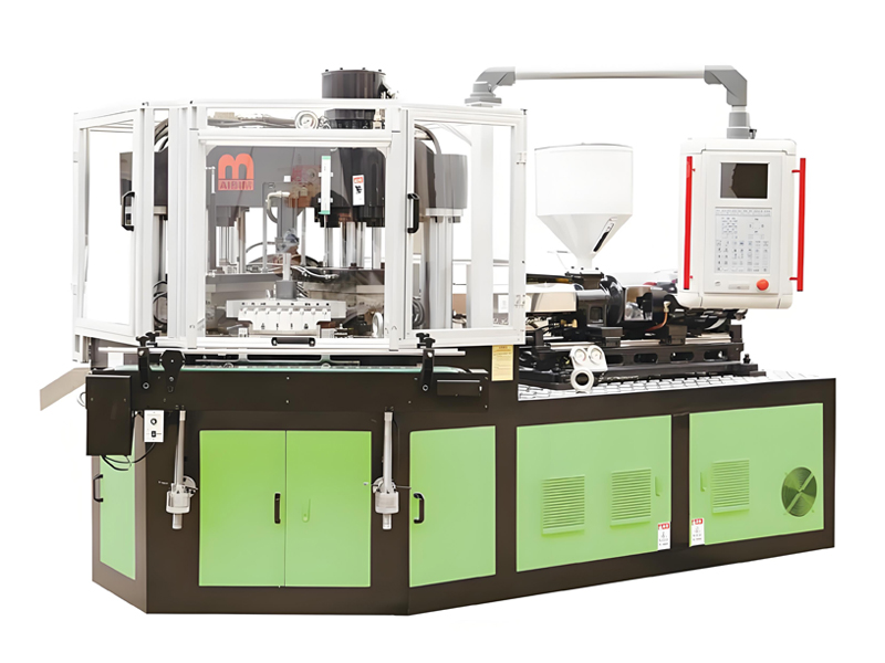
AiBiM injection blow molding machines consist of several integrated systems that work together to produce high-quality plastic products efficiently and consistently. Understanding the function and arrangement of these major components provides the foundation for effective disassembly and assembly procedures. The primary systems include the injection unit, the blow molding station, the hydraulic system, the electrical control system, and the machine frame and clamping system. Each of these systems contains multiple components that may require periodic disassembly for maintenance, inspection, or replacement purposes.
Injection Unit Components
The injection unit is responsible for melting plastic material and injecting it into the mold cavity to form the parison that will be blown into the final product shape. Key components of the injection unit include the hopper, barrel, screw, screw drive motor, injection plunger or screw, check valve, and nozzle assembly. The barrel contains heating elements that melt the plastic material as it is fed from the hopper and processed by the rotating screw. The screw itself serves multiple functions including plasticizing, mixing, and injecting the molten material into the mold. The injection unit requires periodic maintenance including screw removal for cleaning or replacement, barrel inspection, and nozzle maintenance.
The injection unit is mounted on the machine frame and can be positioned for mold changes and maintenance access. Hydraulic or servo motor systems provide the driving force for injection and screw rotation, with precise control over injection speed, pressure, and stroke. Temperature control systems maintain appropriate temperatures throughout the barrel and nozzle to ensure proper material melting and flow. The modular design of AiBiM injection units facilitates maintenance procedures while ensuring proper alignment and connection when reassembled. Understanding the arrangement and function of injection unit components enables technicians to perform maintenance safely and effectively.
Clamping and Blow Molding Station
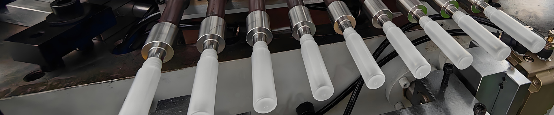
The clamping system secures the mold during the injection and blow molding cycles, with sufficient force to prevent part flash and ensure proper dimensional accuracy. The clamping unit consists of the stationary and moving platens, tie bars that guide and support the platens, the toggle or direct hydraulic clamping mechanism, and the mold mounting surfaces. The blow molding station incorporates the mold cavity, theparison support pins, and the blow air system that expands the molten parison to fill the mold cavity. Proper function of the clamping and blow molding station is essential for achieving quality products consistently.
The blow molding station includes the core rod that supports the parison during the injection and blowing phases, the mold halves that define the final product shape, and the air distribution system that delivers blowing air at appropriate pressure and timing. The mold clamping mechanism may be hydraulic, mechanical toggle, or hybrid combination depending on machine design. Opening and closing the clamping unit for mold changes requires careful attention to safety procedures and proper sequencing. The alignment between mold components, core rod, and blowing systems must be maintained precisely during assembly to ensure proper product formation and quality.
Hydraulic and Electrical Systems
The hydraulic system provides power for clamping, injection, and auxiliary functions in many injection blow molding machines. Components include the hydraulic pump, motor, reservoir, filters, valves, cylinders, and connecting lines and fittings. Hydraulic systems require regular maintenance including fluid level checks, filter changes, and leak inspection. Disassembly of hydraulic components requires attention to pressure relief procedures and proper fluid handling to ensure safety and prevent contamination. AiBiM machines utilize efficient hybrid electric designs that reduce hydraulic system requirements compared to traditional fully hydraulic machines.
The electrical control system manages machine operation through programmable logic controllers, drives, sensors, and operator interface components. Electrical systems include the main power distribution, motor drives for injection and screw rotation, temperature controllers, and the human-machine interface terminal. Electrical disassembly procedures must follow appropriate lockout/tagout procedures to prevent electrical hazards. Only qualified electrical personnel should perform work on electrical components. Understanding the arrangement and connection points of electrical components facilitates efficient maintenance while ensuring safety compliance.
Safety Precautions Before Disassembly
Safety must be the paramount consideration before beginning any disassembly procedure on injection blow molding machines. The combination of heavy components, high pressures, elevated temperatures, and electrical hazards creates multiple potential safety risks that must be addressed through proper planning and procedure. Establishing comprehensive safety protocols and ensuring all maintenance personnel understand and follow these protocols is essential for preventing injuries and equipment damage. This section outlines the critical safety precautions that must be addressed before beginning any disassembly work.
Lockout/Tagout Procedures
Lockout/tagout procedures are required whenever maintenance work involves potential exposure to hazardous energy sources. Injection blow molding machines present multiple energy hazards including electrical power, hydraulic pressure, pneumatic pressure, and stored mechanical energy. The lockout/tagout procedure begins with notifying affected personnel that equipment will be taken out of service for maintenance. The specific equipment to be serviced is identified, and all energy sources are located and documented. Each energy source is then isolated using the appropriate lockout devices, with verification that energy has been effectively isolated before beginning work.
Lockout devices include circuit breakers, valves, and other equipment-specific isolation points that prevent reactivation of energy sources during maintenance. Each person performing maintenance work installs their personal lock on each lockout device, ensuring that no one can energize the equipment without removing all locks. Tagout devices provide additional warning and information about the maintenance status of equipment. Verification procedures confirm that all energy sources have been effectively isolated before physical work begins. Only after completing lockout/tagout procedures and verification can physical disassembly work proceed safely.
Pressure and Temperature Considerations
Hydraulic and pneumatic pressures within injection blow molding machines can cause serious injury if released unexpectedly during disassembly. Before opening any hydraulic or pneumatic lines, pressure must be fully relieved through appropriate procedures. This includes cycling the machine through all functions to release any trapped pressure and verifying with pressure gauges that no residual pressure remains. Hydraulic fluid at operating temperatures can cause burns, and some hydraulic fluids present additional chemical hazards. Appropriate personal protective equipment including heat-resistant gloves and chemical-resistant clothing may be required when working with heated hydraulic systems.
Temperature hazards exist throughout injection blow molding machines, particularly in the injection unit where material temperatures may exceed 250 degrees Celsius. Molten plastic within the barrel and injection system presents severe burn hazards, and proper cooling procedures must be followed before any disassembly involving these areas. Barrel temperatures should be reduced to safe levels over an appropriate time period to avoid thermal shock to heating elements and temperature sensors. The cooling time required depends on barrel size and material, but typically ranges from 30 minutes to several hours for complete cooling. Verification of safe temperatures with appropriate measurement equipment should precede any disassembly involving heated areas.
Personal Protective Equipment Requirements
Appropriate personal protective equipment protects maintenance personnel from hazards encountered during disassembly procedures. Required PPE may include safety glasses or goggles, hearing protection, gloves appropriate for the specific hazards involved, protective footwear, and appropriate clothing that avoids entanglement hazards. Heat-resistant gloves are essential when working near heated components, while chemical-resistant gloves may be required when handling hydraulic fluids or cleaning solvents. Safety shoes with steel toes protect against heavy component handling hazards. Long sleeves and pants provide additional protection but must be secured to avoid catching hazards from rotating equipment.
Additional PPE may be required for specific procedures including hearing protection near loud equipment, respiratory protection when working with dust or fumes, and face shields when working with pressurized systems or molten materials. PPE requirements should be assessed for each specific task as part of the job safety analysis process. All PPE should be inspected before use to verify it is in good condition and provides appropriate protection. Training on proper PPE selection, use, and care ensures that maintenance personnel are protected effectively throughout disassembly and assembly procedures. The investment in appropriate PPE and training represents a minimal cost compared to the potential consequences of workplace injuries.
Disassembly Step-by-Step Process
Systematic disassembly following established procedures ensures that components are removed safely and can be reassembled correctly. The specific disassembly sequence depends on the maintenance task being performed, but general principles apply to most disassembly situations. This section provides guidance on disassembly procedures for common maintenance tasks including mold changes, injection unit maintenance, and general component access. Following these procedures helps ensure safety and maintains equipment integrity throughout the maintenance process.
Mold Change Disassembly Procedures
Mold changes represent one of the most frequent disassembly operations performed on injection blow molding machines. The mold change procedure begins with completing the lockout/tagout process and allowing the machine to cool to safe temperatures if heated mold components are present. The clamping system is opened to provide access to the mold area. Mold clamping devices are released according to manufacturer procedures, typically requiring sequential loosening of mounting bolts in a diagonal pattern to avoid uneven stress. With clamping devices released, the mold can be carefully removed from the machine using appropriate lifting equipment rated for the mold weight.
Lifting equipment must be inspected before use and properly attached to the mold using designated lifting points. Uneven mold weights require careful attention to lift point selection and rigging configuration. Withdraw the stationary mold half first, followed by the moving mold half if applicable. Core rods and other inserts should be removed according to specific procedures for the mold design. Mold mounting surfaces should be cleaned after mold removal, with any damage or wear documented for maintenance action. The removed mold should be stored in designated areas with appropriate protection and identification. Following proper mold change procedures maintains equipment condition and ensures safe transitions between production runs.
Injection Unit Disassembly Procedures
Disassembly of injection unit components requires careful attention to sequence and cleanliness to ensure proper reassembly and continued performance. The process begins with completing all safety procedures including lockout/tagout, cooling the barrel to safe temperatures, and relieving any hydraulic or pneumatic pressure. Material remaining in the barrel should be purged using appropriate purging compound or the intended production material. After purging, the injection unit should be retracted to the fully rear position and secured against movement. The nozzle should be removed using appropriate tools, with care taken to protect the nozzle tip and sealing surfaces from damage.
Screw removal requires specialized puller tools and procedures that vary by machine manufacturer. The general process involves securing the screw rotation mechanism, attaching the puller tool to the screw flange, and applying controlled force to withdraw the screw from the barrel. The screw should be carefully extracted to avoid damage to flight surfaces and to prevent personal injury from the heavy component. After screw removal, barrel inspection and cleaning can proceed using appropriate tools and methods. All removed components should be cleaned thoroughly and inspected for wear, damage, or other conditions requiring attention. Documentation of component condition supports maintenance planning and helps identify patterns that may indicate emerging problems.
Hydraulic System Disassembly Considerations
Hydraulic system disassembly requires specific attention to pressure relief, fluid containment, and component handling to ensure safety and prevent contamination. Before opening any hydraulic connections, verify that all pressure has been relieved through the appropriate procedures. Place collection containers beneath connections to be opened to capture any residual fluid. Removing fittings and connections slowly allows any remaining pressure to release gradually rather than causing fluid spray. Hydraulic fluid should be collected and handled according to facility procedures for used fluid disposal.
Hydraulic cylinders and actuators may contain spring-loaded components or stored pressure that presents hazards during disassembly. Consult manufacturer documentation for specific disassembly procedures and precautions for these components. Seals and gaskets should be inspected during disassembly and replaced as part of normal maintenance rather than reusing potentially worn components. Cleanliness is critical for hydraulic systems, as contamination can cause immediate operational problems and long-term reliability issues. All components should be protected from contamination during disassembly and handled using clean techniques during inspection and reassembly. Replacement seals and gaskets should be verified as correct parts before reassembly begins.
Parts Inspection and Maintenance
Thorough inspection of disassembled parts identifies conditions requiring maintenance action and supports predictive maintenance strategies. Regular inspection following established procedures helps identify problems early, before they cause equipment failures or quality issues. This section provides guidance on inspection procedures and maintenance actions for key injection blow molding components.
Screw and Barrel Inspection
The screw and barrel represent the heart of the injection system and require regular inspection to ensure proper function. Visual inspection of the screw should examine flight surfaces for wear, scratching, or damage that could affect material processing. Wear patterns on flight edges indicate material backflow that reduces injection efficiency. The screw root diameter should be measured and compared to new specifications to determine wear extent. Compression ratio, determined by comparing flight depth at the feed section to the metering section, affects plasticizing performance and should be verified against specifications.
Barrel inspection focuses on the bore surface, checking for wear patterns, scoring, or damage that could affect material flow or cause excessive wear to the screw. Barrel wear typically occurs in the feed and transition zones where material first enters and begins to melt. Borescope inspection allows visual examination of barrel interior conditions without full disassembly. Temperature sensors and heating elements should be tested to verify proper function. Wear measurements and inspection findings should be documented to support maintenance planning and identify trends over time.
Mold Component Inspection
Mold components require inspection for wear, damage, and condition that affects product quality and production efficiency. Cavity and core surfaces should be examined for wear, scratching, pitting, or other damage that could affect product appearance or dimensions. Gating and venting systems require particular attention, as blocked or damaged gates and vents cause quality problems including short shots, flash, and surface defects. Blowing pins and air channels should be inspected for blockage or damage that could affect the blow molding process.
Sealing surfaces between mold halves should be inspected for wear or damage that could cause flash or part quality problems. Guide bushing and wear plate condition affects alignment and should be evaluated as part of regular inspection. Springs, screws, and other mold components should be verified for proper condition and function. The inspection checklist should cover all critical mold features with specific acceptance criteria for each inspection point. Documentation of mold inspection findings supports maintenance scheduling and helps identify patterns indicating emerging problems.
Hydraulic and Pneumatic Component Inspection
Hydraulic components should be inspected for condition that affects system performance and reliability. Pump and motor condition can be assessed through observation of noise, temperature, and flow characteristics. Cylinder rods should be inspected for scoring, wear, and surface condition that affects seal life and function. Valves should be tested for proper operation and response time. Filter elements should be inspected or replaced according to maintenance schedules. Hose and fitting condition should be verified, with any signs of wear, damage, or leakage addressed through replacement.
Pneumatic system inspection focuses on airlines, valves, and actuators that affect machine function. Air line condition should be verified, with any kinks, damage, or leaks addressed. FRL units (filter, regulator, lubricator) should be maintained according to manufacturer recommendations. Cylinder condition and operation should be verified, with attention to speed, force, and smooth operation. Blow air systems for injection blow molding require particular attention, as proper air delivery is essential for product quality. All inspection findings should be documented and compared to acceptance criteria to determine required maintenance actions.
Assembly Process Guidelines
Proper assembly following manufacturer specifications ensures that maintenance actions restore equipment to proper operating condition. Assembly procedures must follow established sequences and torque specifications to ensure correct function and prevent damage. This section provides guidance on assembly procedures for common maintenance tasks, emphasizing the attention to detail required for successful reassembly.
Screw and Barrel Reassembly
Screw reassembly into the barrel requires careful attention to cleanliness, alignment, and proper installation sequence. The screw should be cleaned thoroughly and inspected before installation, with any findings documented. The barrel bore should be inspected and cleaned, removing any debris or contamination that could affect operation. Apply a small amount of appropriate lubricant to the screw flights to facilitate installation, avoiding materials that could contaminate production materials. The screw should be aligned with the barrel bore and carefully inserted using appropriate alignment tools and techniques.
Screw to drive shaft connection must be made according to manufacturer specifications, typically requiring specific torque values applied in the correct sequence. The nozzle should be installed with appropriate sealing, typically using new copper or graphite gaskets that provide heat-resistant sealing. Heater bands and temperature sensors should be connected and verified before energizing the machine. After assembly, the injection unit should be heated to operating temperature and the screw purged before beginning production. Proper reassembly procedures restore injection unit function and ensure continued reliable performance.
Mold Installation Procedures
Mold installation requires careful attention to alignment, clamping, and connection procedures to ensure proper function and safety. Before installing the mold, clean mold mounting surfaces on the machine platens, removing any debris, oil, or contamination. Verify that mounting holes and features are clear and in good condition. Inspect the mold for any damage or wear that occurred during storage or transport. Position the mold for installation using appropriate lifting equipment, ensuring that the mold weight does not exceed lifting equipment ratings. Lower the mold carefully onto the mounting surfaces, ensuring proper alignment with mounting holes.
Secure the mold using appropriate clamping devices, typically starting with light snugging of all bolts before final torque application. Torque specifications for mold mounting typically range from 150 to 250 foot-pounds depending on mold size and machine specifications. After clamping, verify mold alignment using appropriate indicators if required. Connect any auxiliary services such as water lines, air lines, or ejector connections according to mold specifications. Install core rods and other inserts according to the specific mold design requirements. Following installation, perform a mold trial to verify proper function and product quality before resuming production runs.
Hydraulic System Reassembly
Hydraulic system reassembly requires attention to cleanliness, torque specifications, and proper assembly sequence to ensure leak-free, reliable operation. All components should be cleaned thoroughly before assembly, with particular attention to sealing surfaces and fluid passages. New seals and gaskets should be installed as part of normal maintenance rather than reusing potentially worn components. Torque specifications for hydraulic fittings vary by size and type, typically ranging from finger tight followed by specific additional turns or torque values. Overtightening can damage fittings and create leak paths, while undertightening may not provide adequate sealing.
Hydraulic lines should be installed with attention to proper routing and support to prevent chafing, kinking, or stress on connections. Hose installations should allow for appropriate flex and movement without excessive bending or tension. After assembly, the hydraulic system should be pressurized gradually while checking for leaks at all connections. Any leaks found should be addressed immediately by tightening or replacing affected components. System operation should be verified through function tests that exercise all hydraulic functions at operating pressure. Following reassembly, monitor the system closely during initial operation to identify any issues that may not have been apparent during initial leak checking.
Cost Analysis of Maintenance and Spare Parts
Understanding the cost implications of maintenance activities and spare parts enables efficient maintenance planning and budget management. The total cost of ownership for injection blow molding equipment includes significant maintenance costs that can be optimized through effective planning and execution. This section provides cost analysis frameworks for common maintenance components and activities, helping maintenance managers make informed decisions about maintenance strategies and spare parts inventory.
Spare Parts Cost Structure
Spare parts costs for injection blow molding machines include components that wear or fail during normal operation and require periodic replacement. Common wear parts include seals, gaskets, filters, bearings, and other components with finite service lives. Screw and barrel components may require replacement after extended service, representing significant costs that must be planned for in maintenance budgets. Machine wear parts typically represent 2% to 4% of initial machine purchase price annually, though this varies based on production volume, materials processed, and operating practices. Higher-capacity machines typically have proportionally higher spare parts costs due to larger component sizes.
Preventive maintenance parts including filters, oils, and wear components represent predictable costs that can be budgeted based on maintenance schedules. Emergency spare parts for critical components may be maintained in inventory to minimize downtime when failures occur, though this represents additional inventory investment. Spare parts inventory management must balance the cost of carrying inventory against the potential cost of production downtime due to parts unavailability. AiBiM can provide guidance on recommended spare parts inventory levels and typical maintenance cost expectations for their equipment models. Establishing relationships with parts suppliers helps ensure availability and competitive pricing for spare parts over the equipment lifetime.
Maintenance Labor and Service Costs
Maintenance labor costs depend on the skill levels required, the time needed for various procedures, and local labor rates. Routine maintenance activities such as lubrication, filter changes, and inspections can typically be performed by machine operators or entry-level maintenance technicians with appropriate training. More complex maintenance including component replacement and troubleshooting may require skilled maintenance technicians with specialized training and experience. Major maintenance activities may require OEM service technicians or specialized contractors for tasks beyond internal capabilities.
Service contracts with equipment manufacturers or third-party service providers offer alternative approaches to maintenance that can provide predictable costs and access to specialized expertise. Service contract costs typically range from 1% to 3% of equipment purchase price annually, depending on coverage scope and equipment complexity. The value of service contracts depends on factors including the reliability of internal maintenance capabilities, the criticality of equipment to operations, and the availability of external service resources. AiBiM provides technical support and service resources for their equipment, helping owners maintain optimal equipment performance throughout the equipment lifetime.
Common Assembly Errors and Solutions
Awareness of common assembly errors helps maintenance personnel avoid these mistakes and recognize when they have occurred. Assembly errors can cause immediate operational problems, premature failures, or safety hazards that require correction before production can resume. This section identifies common errors and provides guidance on avoiding and addressing them.
Torque and Fastening Issues
Insufficient torque on fasteners represents one of the most common assembly errors, leading to loosening, leakage, and component damage during operation. Establishing clear torque specifications and using appropriate torque control tools helps prevent insufficient torque. Calibration of torque tools ensures that applied torque values are accurate and consistent. Overtightening represents the opposite error, potentially causing stripped threads, damaged components, or compressed seals that fail prematurely. Following manufacturer torque specifications and using calibrated tools helps avoid both insufficient and excessive torque conditions.
Thread damage during assembly can cause future assembly difficulties or component damage. Cross-threading fasteners before proper engagement damages threads and makes proper installation impossible. Starting fasteners by hand to verify proper thread engagement before applying tools helps prevent cross-threading. Using damaged or incorrect fasteners can cause similar problems, making verification of fastener condition and specification an important assembly step. Thread locker compounds may be specified for certain applications and should be applied correctly when required. Paying attention to these details during assembly prevents problems that may not become apparent until equipment is returned to operation.
Alignment and Clearance Issues
Improper alignment during assembly causes binding, premature wear, and performance problems that may require correction and reassembly. Proper alignment tools and procedures help ensure that components are positioned correctly during assembly. Checking alignment at multiple points rather than relying on single-point references provides greater confidence in alignment accuracy. Components that appear aligned visually may still have alignment errors that only become apparent during operation. Using appropriate measurement and alignment techniques prevents alignment-related problems.
Clearance issues arise when components are assembled with insufficient or excessive clearances for proper function. Insufficient clearances can cause binding, heating, or interference that damages components during operation. Excessive clearances can cause misalignment, vibration, or loss of function. Understanding the clearance requirements for specific applications helps ensure appropriate assembly practices. New seals, gaskets, and bearings typically have specific installation instructions regarding clearance requirements. Following these instructions ensures that components function as designed after assembly.
Contamination and Cleanliness Problems
Contamination introduced during assembly causes immediate operational problems and long-term reliability issues that may not become apparent until after extended operation. Foreign material in hydraulic systems can cause valve sticking, pump damage, and seal failures throughout the system. Material contamination in injection units can cause product quality problems and equipment damage. Thorough cleaning of all components before assembly and protection of open connections during assembly prevents contamination introduction. Working in clean environments and using clean tools for assembly maintains the cleanliness necessary for reliable operation.
Seal installation requires particular attention to cleanliness, as contamination on seal surfaces can cause immediate leakage or premature failure. Seals should be inspected for damage before installation and handled carefully to avoid introducing scratches or deformation. Proper seal installation tools help ensure correct seal positioning without damage. Lubrication of seals during installation facilitates proper seating and prevents damage. Taking time to ensure cleanliness and proper seal installation pays dividends in reduced leakage problems and extended seal life after equipment is returned to service.
Technical Documentation and Support
Access to accurate technical documentation and manufacturer support enables effective maintenance and troubleshooting throughout equipment lifetime. AiBiM provides comprehensive documentation and support resources for their injection blow molding machines, helping owners maintain optimal equipment performance. Understanding available documentation and support resources helps maintenance personnel work more effectively.
Operation and Maintenance Manuals
Operation and maintenance manuals provide essential information for safe, effective equipment operation and maintenance. Manuals typically include safety precautions, operating procedures, maintenance schedules, troubleshooting guides, and parts lists. Maintenance personnel should be thoroughly familiar with relevant manual content before performing maintenance activities. Manuals should be maintained in accessible locations and kept current with any updates or supplements provided by the manufacturer. Digital copies of manuals may be available from AiBiM, providing backup access and search capabilities that facilitate maintenance activities.
Parts lists within manuals identify recommended spare parts with part numbers and ordering information. Maintaining adequate supplies of critical spare parts based on parts list recommendations helps ensure that maintenance can be performed without delay due to parts unavailability. Exploded view diagrams and assembly drawings facilitate disassembly and assembly procedures by showing the relationship between components. Electrical schematics and hydraulic diagrams support troubleshooting and repair of these systems. All documentation should be secured against damage and maintained in legible, complete condition.
Manufacturer Technical Support
Manufacturer technical support provides access to expertise that can assist with troubleshooting, maintenance planning, and complex repair procedures. AiBiM provides technical support services for their equipment, helping owners address maintenance challenges and optimize equipment performance. Support may be available through various channels including phone, email, and online resources. Understanding how to access support and what information to provide facilitates efficient resolution of technical issues. AiBiM’s experience across more than 40 countries provides broad perspective on equipment operation and maintenance that can benefit owners facing unusual challenges.
Training programs offered by AiBiM help develop maintenance skills and knowledge that enable personnel to perform maintenance more effectively. Training covers topics including operation, programming, maintenance procedures, and troubleshooting. Both initial training for new personnel and refresher training for experienced staff contribute to maintenance effectiveness. Documentation of training completion supports qualification verification and helps ensure that personnel are prepared for their maintenance responsibilities. Investing in training pays returns through improved maintenance quality, reduced downtime, and extended equipment life.
Conclusion
Proper disassembly and assembly of injection blow molding machine parts represents a critical skill set that contributes to equipment reliability, production efficiency, and workplace safety. The comprehensive procedures outlined in this guide provide the foundation for effective maintenance practices that protect equipment investment and support successful manufacturing operations. Attention to safety precautions, systematic procedures, and quality standards throughout disassembly and assembly activities prevents equipment damage, quality problems, and safety incidents that can result from improper practices.
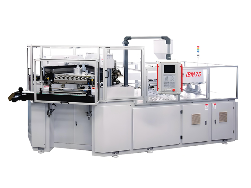
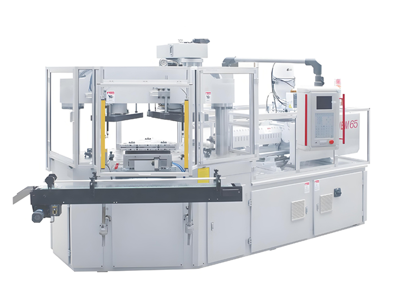
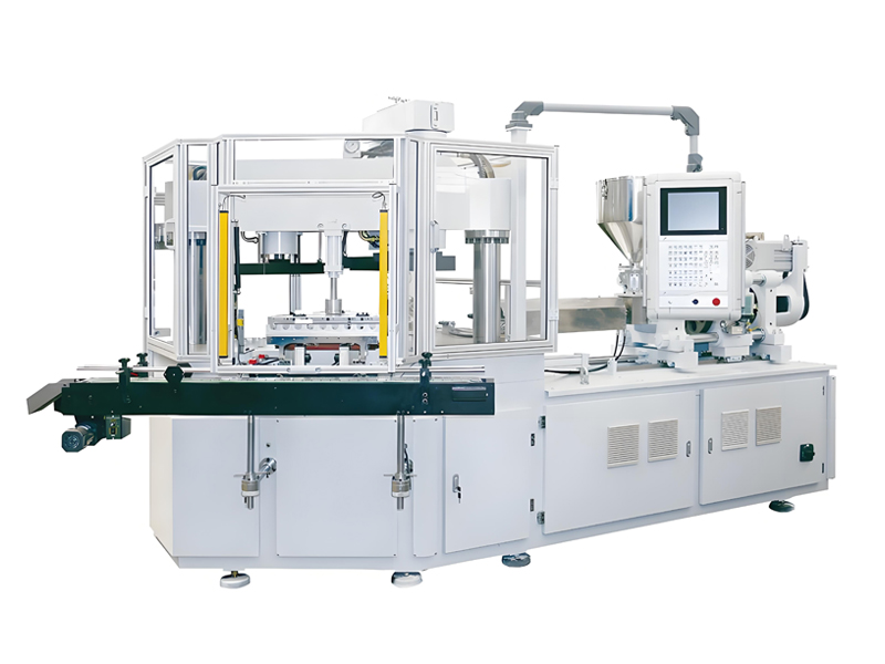
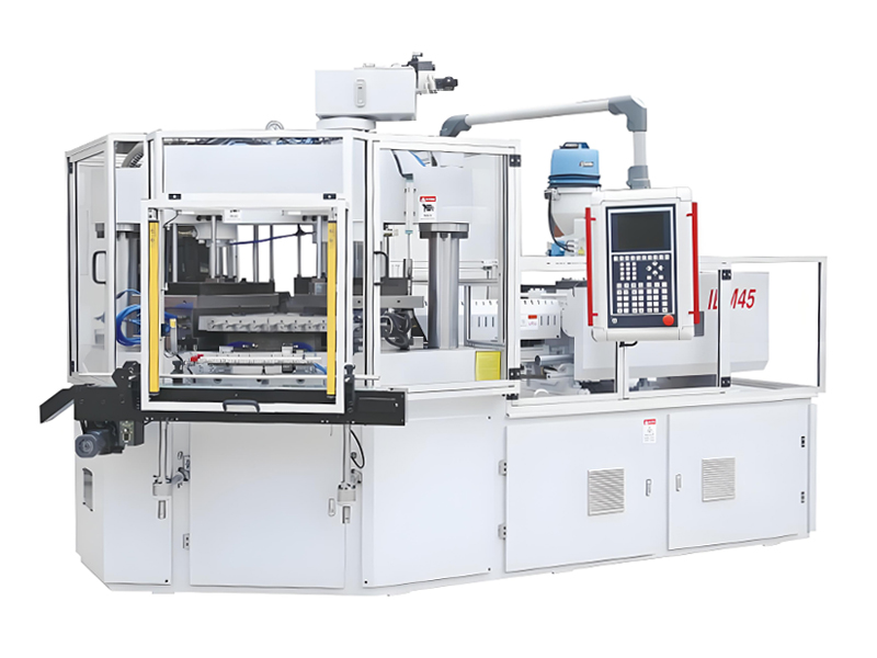
AiBiM’s injection blow molding machines, including the IBM55, IBM65, and IBM75 models, are designed with maintenance accessibility in mind, facilitating efficient disassembly and assembly while ensuring proper function after maintenance activities. The company’s comprehensive documentation and technical support resources help owners develop and maintain effective maintenance capabilities. With over 12 years of manufacturing experience and exports to more than 40 countries, AiBiM has developed the expertise needed to support maintenance personnel in developing the skills required for effective equipment care.
Success in injection blow molding equipment maintenance requires commitment to safety, investment in training and resources, and attention to detail throughout all maintenance activities. The cost of proper maintenance practices is always less than the cost of equipment failures, quality problems, and safety incidents that result from neglected or improper maintenance. By implementing the procedures and practices outlined in this guide, maintenance personnel can contribute to equipment reliability, production success, and workplace safety. The ongoing commitment to maintenance excellence creates sustainable competitive advantages for manufacturing facilities committed to operational excellence in injection blow molding production.