Bottle plants rarely fail because a machine is slow. They fail because the building around the machine was drawn by someone who was solving a parking problem — how do we fit the equipment inside these walls — instead of an engineering problem. A plastic bottle factory layout design that only proves the machines physically fit will look brilliant on opening day and will be choking on its own material flow within three years. Pallets will be staged in aisles, the mold change crew will wait for a forklift, the drying room will sit forty meters from the hoppers, and the electrical room sized precisely for the first four machines will block the fifth.
The alternative is not more space. It is a layout built by overlaying three separate drawings on the same building grid: a material flow diagram, a cleanliness zoning diagram, and a utility distribution diagram. Where the three agree, you have a good layout. Where they conflict, you have found a problem that is cheap to fix on paper and brutally expensive to fix in concrete. This guide walks through that overlay method specifically for injection blow molding (IBM) bottle production, with quantified rules — square meters, millimeters, meters per second, air changes per hour, kilonewtons per square meter — rather than generic advice.
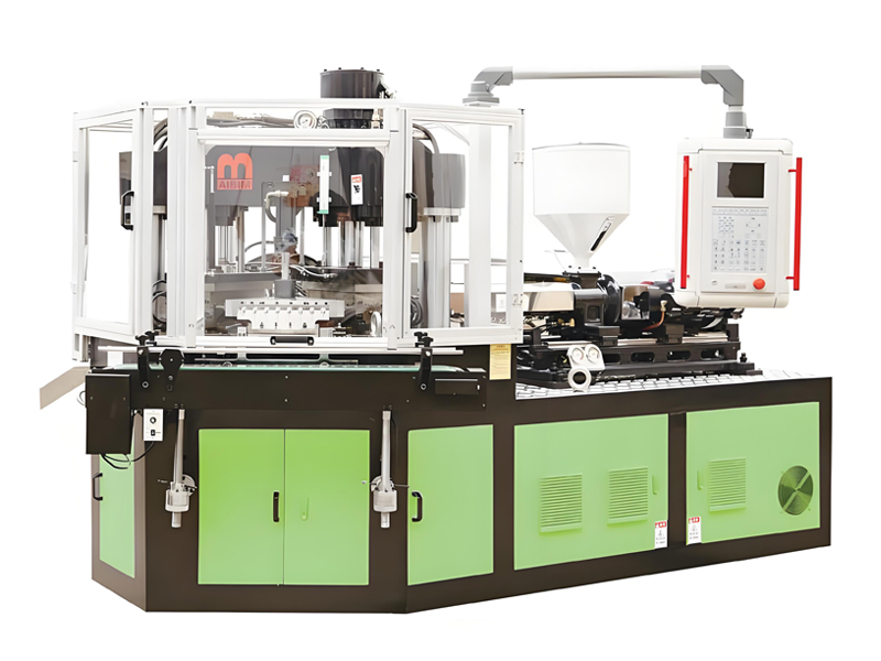
The technical reference point throughout is the IBM three-station one-step process, the dominant route for small rigid bottles and jars in pharmaceutics, food, drink and cosmetic packaging. Aibim, a Wanplas factory, has spent more than twelve years building injection blow molding machines and molds for exactly this product window — containers from 3 ml to 1000 ml — and now ships to more than forty countries from a plant acquired in 2022 with an annual capacity above one hundred machine sets and its own CNC machining center for critical components. Layout drawings, machine foundation drawings and utility connection schedules are part of what Aibim and the wider Wanplas engineering group put in front of a customer before the first concrete is poured, precisely because the building decisions outlive the machines by decades.
- Perché gli errori di layout sono permanenti e costosi
- Modello del flusso di materiali per uno stabilimento di bottiglie IBM
- Metodo di dimensionamento dell'area in base al numero di linee
- Regole di distanziamento e spazio libero delle macchine
- Serie di macchine IBM Aibim e la loro impronta reale
- Disposizione della sala apparecchiature ausiliarie
- Ausiliari centralizzati rispetto a quelli a bordo macchina
- Layout delle tubazioni dell'acqua di raffreddamento
- Distribuzione dell'aria compressa
- Layout elettrico e stima del carico
- Zonizzazione della pulizia per flaconi farmaceutici e cosmetici
- Flusso di lavoro di estrazione, trasporto e imballaggio
- Stoccaggio degli stampi e flusso di lavoro del cambio stampo
- Dimensionamento del magazzino per resina e bottiglie finite
- Ventilazione, rumore e carico termico
- Dal requisito al modello e raccomandazione di layout
- Tre modelli di layout: I, L e U
- Progettazione della riserva di espansione
- Errori comuni di layout e correzioni
- Servizio e supporto da Aibim
- Domande frequenti
- Conclusione
1. Perché gli errori di layout sono permanenti e costosi
Almost every operating decision in a bottle plant can be reversed. You can change resin grade, re-cut a gate, re-time the blow, retrain an operator, replace a chiller. What you cannot reverse cheaply is anything cast into the floor, welded into the structure, or buried in a trench. That asymmetry is the single most important idea in plastic bottle factory layout design: spend disproportionate engineering effort on the irreversible ten percent.
Cinque errori causano la maggior parte dei danni osservati negli stabilimenti IBM esistenti. Ciascuno è invisibile durante la costruzione e doloroso per l'intera vita dell'edificio.
Distanza tra le colonne troppo ridotta per la movimentazione dello stampo
IBM tooling is a three-part set — injection core and neck tooling, blow cavity, and stripper station components — mounted on a common clamping frame. A complete set for a multi-cavity 500 ml bottle can exceed one tonne. If the structural bay is 6 m by 6 m and the crane hook cannot travel over the mold area of every machine, the mold change becomes a forklift-and-prayer operation. Correct practice is a clear structural bay of at least 9 m in the machine direction and 12 to 18 m across the span, with the crane runway positioned so the hook covers the mold face of every machine plus the mold staging area and the truck bay.
Locale ausiliario troppo lontano dalle macchine
Central drying and central feeding are excellent ideas until the conveying line exceeds the physics. Vacuum conveying of pellets is reliable up to roughly 30 m of equivalent length including bends; beyond that, pressure drop, pellet fracture and blockage risk rise sharply. A drying room parked in a corner 55 m from the last machine will generate a permanent daily blockage ritual. Keep the central material room within a 25 to 30 m radius of the furthest hopper, or plan a relay station from the beginning.
Zona pulita e zona di confezionamento che condividono un corridoio
The moment a carton pallet, a forklift and a warehouse operator pass through the same door as the bottles leaving the take-out station, the cleanliness classification of the production area is decorative rather than real. Separate personnel and material routes with dedicated airlocks are not optional for pharmaceutical or cosmetic primary packaging, and retrofitting them into a finished shell means demolishing walls, re-balancing the air handling system, and re-validating the zone.
Locale elettrico dimensionato solo per la prima fase
Transformer rooms and main distribution boards are frequently sized to the exact first-stage connected load with no margin. Adding a fifth and sixth line then requires a second transformer, a second incoming feeder, and often an outdoor substation extension with utility approval. Sizing the transformer room civil shell — not necessarily the transformer itself — for double the initial capacity is one of the highest-return decisions in the whole building.
Nessun corridoio di espansione riservato
Plants that grow by filling every gap eventually lose their main aisle. A layout should nominate, on day one, a specific strip of floor that stays empty: the future machine row, the future utility riser, the future warehouse extension direction. Painting it and defending it is cheaper than any later reconstruction.
2. Modello del flusso di materiali per uno stabilimento di bottiglie IBM
A good bottle plant has one direction of travel. Resin enters at one end of the building, product leaves at the other, and no stream ever doubles back across another. Unidirectional flow eliminates the two most common sources of chaos: cross-traffic between forklifts and operators, and mix-ups between raw, in-process and released material.
The canonical IBM material flow is: resin receiving → central drying room → hopper loading → IBM machine → take-out and conveyor → in-line QC (leak test and vision inspection) → accumulation table → bagging or boxing → finished goods warehouse. Every one of those nine steps has a conveying method, a sensible distance band and a buffer requirement. When any buffer is undersized, a stoppage in one step immediately stops the machine, and IBM machines dislike stopping — a cold start after an unplanned halt wastes purge material and produces a batch of rejects.
| Process step | Conveying method | Recommended distance (m) | Buffer capacity (minutes of production) | Layout note |
|---|---|---|---|---|
| Resin receiving and unloading | Forklift, pallet truck, or bulk bag hoist | Truck dock within 10-20 m of raw material store | 15-30 days as inventory | Dedicated dock, no shared route with finished goods |
| Raw store to central drying room | Bulk bag discharge station plus vacuum conveying | 10-25 | 4-8 hours in day bins | Keep the store adjacent to the material room wall |
| Drying and dehumidifying | Dehumidifying dryer with insulated hopper | Hopper on the dryer skid | 3-4 times hourly throughput | Dew point monitoring at hopper inlet |
| Dry resin to machine hopper | Vacuum conveying, central feeding manifold | Maximum 30 equivalent length | 20-40 minutes at machine hopper | Insulated or heat-traced line for hygroscopic resin |
| IBM molding | Three-station one-step, no intermediate handling | Not applicable | Not applicable | The parison never leaves the core rod |
| Take-out and discharge | Stripper station plus chute or belt conveyor | 2-4 to the first conveyor | 1-2 | Discharge height matched to conveyor belt height |
| In-line QC: leak and vision | Belt conveyor through inspection stations | 4-8 | 2-3 | Reject chute with lockable reject bin |
| Accumulation table | Rotary or belt accumulator | 2-4 | 10-15 | Sized so packing breaks never stop the machine |
| Bagging or boxing | Manual or semi-automatic packing station | 3-6 to pallet build position | 30-60 as staged pallets | Ergonomic work surface, carton supply from behind |
| Finished goods transfer | Pallet truck or forklift | 15-40 | 7-15 days as inventory | Airlock if the hall is a controlled area |
Three numbers in that table carry more weight than the rest. The 30 m vacuum conveying limit sets where the drying room can physically be. The 10 to 15 minute accumulation buffer decides whether the machine keeps running during a packing changeover, a shift handover, or a carton shortage. And the discharge height of the take-out station determines whether your conveyors run flat and clean or climb awkwardly over an aisle.
One further discipline: never let the reject stream share a route with good product. A locked reject bin at the inspection station, emptied by quality staff and not by production, is the simplest defense against reworked bottles finding their way into a released pallet. For pharmaceutical work this is not just good practice, it is what auditors expect to see drawn on the layout.
3. Metodo di dimensionamento dell'area in base al numero di linee
Most bottle plant area estimates start from the wrong end — the size of a plot that happens to be available. The engineering method runs the other way: decide the number of IBM lines you intend to operate at maturity, size every functional zone from that line count, then add circulation and only then look for a building.
The table below gives working figures for a plant built around IBM75-class machines producing containers in the 50 ml to 1000 ml range, running two or three shifts. Zones are net functional areas; circulation aisles are already distributed into the production hall figure but not into the warehouse figures, where racking layout governs.
| Zone | 1 line | 2 lines | 4 lines | 8 lines |
|---|---|---|---|---|
| Production hall including aisles (m²) | 250 | 420 | 750 | 1,400 |
| Drying and auxiliary room (m²) | 40 | 60 | 110 | 200 |
| Mold storage and mold workshop (m²) | 40 | 60 | 100 | 180 |
| Raw material warehouse (m²) | 60 | 100 | 180 | 320 |
| Finished goods warehouse (m²) | 120 | 220 | 420 | 800 |
| QC laboratory (m²) | 20 | 25 | 40 | 60 |
| Utility room: transformer, compressor, chiller (m²) | 40 | 60 | 100 | 180 |
| Total production footprint (m²) | 570 | 945 | 1,700 | 3,140 |
| Minimum clear height under crane hook (m) | 6.0 | 6.5 | 7.0 | 8.0 |
| Overhead crane capacity (t) | 3 | 5 | 5 | 10 |
| Recommended structural bay (m) | 9 × 12 | 9 × 15 | 9 × 18 | 9 × 21 |
| Slab design loading, production hall (kN/m²) | 25 | 25 | 30 | 30 |
Read the total footprint row as production area only. Offices, meeting rooms, changing rooms, canteen, maintenance workshop and site circulation typically add another 20 to 30 percent on top. A four-line plant therefore realistically occupies 2,100 to 2,250 m² of covered building, before yard, parking and truck maneuvering space.
Two rows deserve comment. Clear height is measured under the crane hook, not to the underside of the roof structure — a common and expensive misreading. A 6 m clear hook height allows an IBM machine 2.3 m tall, a mold set slung 1.2 m below the hook, and safe passage over adjacent equipment. Slab loading of 25 to 30 kN/m² covers both the machines themselves and, more critically, the point loads under racking legs in the warehouse zones, which are often the governing case.
4. Regole di distanziamento e spazio libero delle macchine
Clearance around a molding machine is not empty space — it is working space, and every millimeter of it has a named user. Cut it, and you have not saved floor area; you have moved a cost from the building budget to the daily operating budget in the form of slower mold changes, awkward maintenance and safety incidents.
The rules below apply to IBM machines specifically. Compared with a general injection molding machine, an IBM unit needs more room on the mold change side because three tool stations are removed and installed as a coordinated set, and more room at the discharge end because the stripper station and conveyor take-off sit outboard of the clamping frame.
| Clearance item | Minimum | Recommended | Why this dimension exists |
|---|---|---|---|
| Operator side (control panel side) | 1,500 | 1,800 | Operator standing position, panel access, tool trolley |
| Non-operator side | 1,000 | 1,200 | Maintenance access, guarding, cable and hose runs |
| Mold change side | Platen width + 1,200 | Platen width + 1,800 | Full withdrawal of the tool set plus cart standing room |
| Rear, hydraulic and electrical cabinet side | 1,000 | 1,300 | Cabinet door swing, pump access, oil cooler airflow |
| Discharge end, stripper and conveyor | 2,000 | 2,500 | Conveyor take-off, chute, inspection access |
| Machine centerline spacing, IBM75 class | 4,500 | 5,000 | Two machines back to back with shared service alley |
| Machine centerline spacing, IBM55 class | 3,800 | 4,200 | Smaller frame, still needs full mold change room |
| Aisle width, pallet truck only | 2,000 | 2,200 | Loaded pallet plus operator walking clearance |
| Aisle width, counterbalance forklift | 3,500 | 3,800 | Turning radius with a loaded pallet at height |
| Main plant spine aisle | 3,500 | 4,000 | Two-way traffic and emergency egress |
| Vertical clearance above machine to crane hook path | 1,500 | 2,000 | Mold set slung under hook clears machine top guarding |
| Clearance to a fixed wall behind a machine | 1,200 | 1,500 | Cooling airflow and inspection walkway |
The mold change side rule is the one most often violated. Writing it as “platen width plus 1,200 mm” rather than a fixed number keeps it correct across machine sizes: a machine with a 900 mm platen needs 2,100 mm minimum on that side, and one with a 1,150 mm platen needs 2,350 mm. If the mold change side faces a wall, the whole machine has to be shuffled sideways every time the tooling changes, which in practice means the plant stops doing quick changes and starts running long, inflexible campaigns.
Real occupancy is always larger than the machine outline in the catalog because the auxiliaries and the safety fence travel with the machine. The table below gives the practical cell size to reserve on a layout drawing for each Aibim model, including machine-side mold temperature controllers, the take-out chute, the local control cabinet and a perimeter safety fence with light curtain at the operator opening.
| Model | Machine outline L × W (mm) | Cell to reserve L × W (mm) | Cell area (m²) | Cell area with share of service aisle (m²) |
|---|---|---|---|---|
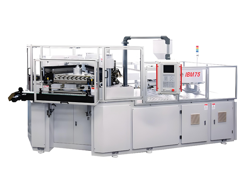
| IBM75 | 5,200 × 1,900 | 8,200 × 5,200 | 42.6 | 52 |
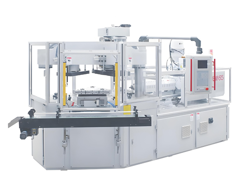
| IBM65 | 4,600 × 1,750 | 7,400 × 4,900 | 36.3 | 45 |
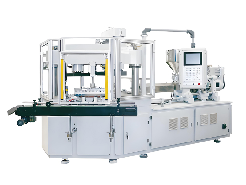
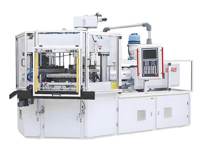
| IBM55 Hybrid Electric | 4,200 × 1,650 | 6,800 × 4,600 | 31.3 | 39 |
Notate come l'ultima colonna — area della cella con una quota proporzionale del corridoio di servizio — sia dal 20 al 25 percento più grande della cella recintata stessa. È quella quota a fare la differenza tra un layout che sembra fattibile in un programma di disegno e uno che funziona con un transpallet al suo interno.
5. Serie di macchine Aibim IBM e la loro impronta reale
Layout work needs machine data early, because the machine sets the cell size, the crane capacity, the electrical load, the cooling load and the compressed air demand simultaneously. Aibim, a Wanplas factory, builds three injection blow molding platforms covering the full 3 ml to 1000 ml container window, all using the three-station one-step process in which injection, blowing and stripping happen on a single rotating core rod set with no intermediate handling of the parison.
All three platforms share the same structural philosophy: a single-crossbeam, double-pole clamping framework that enlarges the usable mold setting space compared with conventional four-pole frames, CE-compliant safety with a light curtain at the operator opening and a long-distance digital laser sensor on the stripper station for mold protection, and Aibim’s PREFILL hydraulic technology combined with variable displacement pump pressurizing, which delivers a minimum 35 percent reduction in energy consumption against conventional fixed-pump hydraulics. Machine parameter sets can be exported to an SD card and reloaded on another machine of the same model, which matters enormously in a multi-line plant where the same bottle may be produced on any of four machines.
| Parameter | IBM75 | IBM65 | IBM55 Hybrid Electric |
|---|---|---|---|
| Clamping force (kN) | 750 | 650 | 550 |
| Maximum product volume (ml) | 1,000 | 500 | 250 |
| Minimum product volume (ml) | 20 | 10 | 3 |
| Stations | 3 (injection / blow / stripper) | 3 (injection / blow / stripper) | 3 (injection / blow / stripper) |
| Typical cavity range | 1-8 | 2-12 | 4-16 |
| Machine dimensions L × W × H (mm) | 5,200 × 1,900 × 2,300 | 4,600 × 1,750 × 2,250 | 4,200 × 1,650 × 2,200 |
| Machine weight (t) | 9.5 | 7.5 | 6.2 |
| Installed power (kW) | 55 | 45 | 34 |
| Footprint including clearance (m²) | 42.6 | 36.3 | 31.3 |
| Static floor loading (kN/m²) | 15 | 13 | 12 |
| Recommended crane capacity for tooling (t) | 3 | 2 | 2 |
| Drive concept | Hydraulic with PREFILL and variable displacement pump | Hydraulic with PREFILL and variable displacement pump | Hybrid electric, servo-driven plasticizing |
Scelta tra le tre piattaforme dal punto di vista del layout
The IBM75 is the workhorse for larger containers — 250 ml to 1000 ml bottles and jars in food, drink and household chemical packaging. Its bigger clamping frame and 3 t tooling weight are the reason the crane and structural bay recommendations in Table 2 exist. If the product mix ever includes 1000 ml containers, size the building for the IBM75 even if the first machine ordered is smaller.
The IBM65 sits in the middle: 10 ml to 500 ml, comfortable in cosmetic and pharmaceutical work, and a good fit where cavity counts of six to twelve give the required output without moving to the largest frame. It occupies about 15 percent less cell area than the IBM75 and draws roughly 18 percent less installed power.
The IBM55 Hybrid Electric is the small-container specialist, reaching down to 3 ml vials and dropper bottles with cavity counts up to sixteen. Its hybrid electric drive is the quietest and coolest of the three, which changes the layout in two useful ways: hall ventilation load per line falls, and the machine is easier to place inside a classified controlled area where heat and hydraulic oil are unwelcome. For a pharmaceutical bottle room, that is a meaningful advantage.
Materiali e prodotti finali attorno ai quali sono costruite queste macchine
Aibim IBM machines process PE in HDPE, LDPE and LLDPE grades, PP, PS, ABS, SAN, TPU, PC and PCTG. In layout terms, the resin list matters because it decides your drying strategy: PE, PP and PS are non-hygroscopic and tolerate simple hot-air drying or none at all, while PC, PCTG, ABS, SAN and TPU are hygroscopic and demand dehumidifying dryers with a dew point of minus 40 degrees Celsius and controlled residence time. A plant that intends to run PC or PCTG needs a materially larger and better-ventilated drying room than one running only PE and PP.
The end products are concentrated in four industries: pharmaceutics — tablet containers, syrup bottles, dropper bottles, nasal spray bodies; food — spice jars, sauce bottles, condiment containers; drink — small juice and dairy bottles; and cosmetic — lotion bottles, serum bottles, cream jars, deodorant containers. Each of those four has a different cleanliness expectation, which is the subject of section 11 and one of the three overlay drawings.
6. Layout del locale delle attrezzature ausiliarie
The auxiliary room is where good plants and mediocre plants diverge. In a mediocre plant, dryers, chillers and compressors are scattered wherever there was room, each adding heat and noise to the production hall. In a good plant, they live in purpose-built rooms with their own ventilation, their own acoustic treatment, and short, clean utility runs into the hall.
The table below sizes the three principal auxiliary systems per IBM75 line, assuming a throughput in the region of 45 to 60 kg per hour of PE or PP. Scale roughly linearly for line count, with a diversity allowance of 0.8 to 0.9 on chilled water and compressed air when four or more lines run the same product family.
| Equipment | Sizing basis per IBM75 line | Typical capacity | Power (kW) | Space required (m²) | Noise level (dB) | Ventilation requirement |
|---|---|---|---|---|---|---|
| Dehumidifying dryer with drying hopper | 3-4 times hourly throughput as hopper volume | 150-200 L hopper, dew point -40 °C | 12-18 | 3.5-4.5 | 66-70 | Room air change 8-10 per hour, regeneration exhaust ducted outside |
| Hot air dryer (non-hygroscopic resin) | 2-3 times hourly throughput | 100-150 L hopper, 80-100 °C | 6-9 | 2.0-3.0 | 62-66 | Room air change 8-10 per hour |
| Water-cooled chiller, blow mold circuit | 0.6-0.8 kW cooling per kg/h throughput | 40-50 kW cooling, 8-15 °C supply | 14-18 | 6-8 | 72-78 | Separate plant room, 10-15 air changes per hour |
| Cooling tower or dry cooler | Chiller cooling load plus compressor rejection | 70-90 kW heat rejection | 3.0-5.5 | 6-9 (outdoor) | 62-68 | Outdoor, unobstructed airflow on all sides |
| Screw air compressor with inverter drive | 1.5-3.0 m³/min free air per line at 0.8-1.0 MPa | 3.0 m³/min, 1.0 MPa | 22-37 | 8-12 | 75-82 | Dedicated acoustic room, 15-20 air changes per hour, hot air ducted out |
| Refrigerated air dryer, filters and receiver | 1.2-1.5 times compressor flow | 3.6 m³/min, pressure dew point 3 °C | 1.2-2.0 | 3-5 | 60-65 | Same room as compressor, drainage to trapped floor gully |
| Mold temperature controller, injection side | 1-2 units per machine, 15-40 °C zone | 9-12 kW heating, 60 L/min | 9-12 | 0.6 (machine-side) | 58-62 | Machine-side, no separate room needed |
| Central feeding and vacuum conveying station | One station per 4-6 machine hoppers | Conveying velocity 18-22 m/s | 5.5-7.5 | 4-6 | 70-75 | In material room, filter cleaning access on three sides |
| Granulator for sprue and reject bottles | 1 unit per 2-4 lines | 30-80 kg/h | 7.5-15 | 4-6 | 82-88 | Acoustically enclosed, dust extraction to cartridge filter |
Two design decisions follow directly from this table. First, the compressor and the granulator are the two noise sources above 80 dB, and both belong outside the production hall in rooms with masonry walls of at least 200 mm and acoustically treated doors. Second, the chiller and the compressor together reject something like 70 to 90 kW of heat per line; if that heat is dumped into the hall, the hall ventilation system has to remove it again at additional cost. Duct it out at source.
The internal arrangement of the material room follows a simple hierarchy: bulk bag discharge or sack tipping station at the wall nearest the raw store, day bins above the dryers, dryers in a row with 800 mm maintenance clearance between units, and the central feeding manifold on the hall-facing wall so conveying lines run in the shortest possible path. Put the filter and receiver units where a maintenance technician can reach them from a standing position, not on top of a hopper requiring a ladder.
7. Ausiliari centralizzati vs ausiliari a bordo macchina
La questione centrale-versus-lato-macchina è decisa dal numero di linee e dal mix di prodotti, non dalla preferenza. Sotto le tre linee, gli ausiliari lato macchina vincono per semplicità e intensità di investimento. Da tre o quattro linee in su, la centralizzazione ripaga in termini di energia, spazio a pavimento e ambiente del capannone.
| Criterion | Central system | Machine-side system |
|---|---|---|
| Floor area in production hall | Minimal; equipment sits in a separate room | 2-4 m² per machine consumed inside the hall |
| Energy consumption | Lower; diversity and inverter control across the whole plant | Higher; each unit sized for peak with no sharing |
| Hall heat load | Low; heat rejected in the plant room | High; every dryer and pump heats the hall |
| Hall noise level | Low; noise contained in the plant room | Elevated; loaders and dryers add 4-8 dB at the operator position |
| Maintenance | Concentrated, one route, easier planning | Distributed, more units, more filter changes |
| Flexibility for material changes | Lower; a resin change affects a shared line | Higher; each machine is independent |
| Contamination risk between products | Higher without dedicated lines and purge routines | Low; physically separate paths |
| Investment intensity | High at installation, Low per line as line count rises | Low at installation, High per line at scale |
| Compatibilità con la camera bianca | Excellent; equipment outside the classified zone | Poor; each unit is a particle and heat source inside the zone |
| Best suited to | 4 lines and above, or any classified production area | 1-3 lines, frequent material changes, pilot production |
Limiti delle linee di trasporto che vincolano il layout
L'alimentazione centralizzata funziona solo se la fisica del trasporto funziona. Tre numeri governano la progettazione:
- Lunghezza equivalente massima: circa 30 m per il trasporto pneumatico a vuoto a singolo stadio. La lunghezza equivalente significa tratto rettilineo più un'allocazione per ogni curva — considerate una curva a 90 gradi a raggio lungo come circa 3-4 m di tubo rettilineo. Un layout con quattro curve e 20 m di tratto rettilineo è già al limite.
- Velocità di trasporto: da 18 a 22 m/s. Sotto i 18 m/s i granuli si depositano e la linea si intasa al riavvio. Sopra i 22 m/s si generano capelli d'angelo con il PE e fini con PS e PC, che finiscono entrambi come puntini o striature nere in una bottiglia trasparente.
- Diametro della linea: in genere da 38 mm a 51 mm di diametro esterno per portate di trasporto da 200 a 800 kg/h, in acciaio inossidabile con curve a raggio lungo e gomiti in vetro nei punti di usura.
If a machine sits beyond 30 m equivalent length, you have three options: relocate the material room, add an intermediate relay receiver with its own vacuum pump, or accept a machine-side loader fed from a local day bin. The wrong option is to install a longer line and hope. Blockages in a conveying line stop the machine and, in a classified zone, force operators to open pipework inside a controlled area to clear them.
8. Disposizione delle tubazioni dell'acqua di raffreddamento
Cooling water decides bottle cycle time and bottle quality, and its piping decides whether every machine gets the same water. In an IBM plant, poor hydraulic balance across the water network shows up as one machine producing perfect bottles and another, on the identical tool, producing bottles with sink marks and dimensional drift.
Disposizione ad albero rispetto a disposizione ad anello
A tree (branch) layout runs a single main header down the hall with tees dropping to each machine. It is cheap and simple, and it is inherently unbalanced: the machine nearest the pump gets the most flow, the machine at the end gets the least, and adding a machine at the end makes the imbalance worse. A loop (ring) layout brings the header back to the plant room so every machine is fed from two directions. Flow imbalance drops sharply, pressure at the last take-off point stays close to the first, and a section can be isolated for maintenance without shutting the whole hall.
| Aspect | Tree (branch) layout | Loop (ring) layout |
|---|---|---|
| Pressure at the furthest machine | Falls noticeably with distance | Nearly equal to the first machine |
| Balancing effort | Requires balancing valves and repeated adjustment | Largely self-balancing, fine trim only |
| Adding a machine later | Degrades flow for existing machines | Absorbed with minimal disturbance |
| Isolation for maintenance | Downstream machines stop | Section valves allow partial isolation |
| Pipe quantity and investment intensity | Low | Medium |
| Recommended for | 1-2 lines, no expansion planned | 3 lines and above, or any plant with expansion intent |
Parametri di progettazione che devono comparire sul disegno
- Velocità da 1,5 a 2,5 m/s nelle tubazioni principali e di derivazione. Sotto 1,5 m/s, il sedimento si deposita e lo scambio termico ne risente; sopra 2,5 m/s, aumentano la caduta di pressione e l'erosione-corrosione, e la tubazione diventa udibile.
- Differenza di temperatura di ritorno da 3 a 5 gradi Celsius. Una differenza più ampia significa che il flusso è troppo basso; una più ridotta significa che si pompa più acqua di quanta lo stampo possa utilizzare, sprecando energia della pompa.
- Pressione differenziale su ogni macchina da 0,15 a 0,30 MPa, misurata tra i raccordi rapidi di mandata e ritorno, con un manometro sul collettore così gli operatori possono vederla.
- Two temperature zones. Injection molds run warm — typically 15 to 40 degrees Celsius depending on resin — and are best served by mold temperature controllers. Blow molds run cold, typically 8 to 15 degrees Celsius from the chiller, because the bottle must set before ejection. Mixing these two circuits into one loop is the single most common cooling design error in bottle plants.
- Isolamento su tutte le linee refrigerate con isolamento a celle chiuse a tenuta di vapore di 19-25 mm. I collettori refrigerati non isolati in un capannone umido gocciolano continuamente sul pavimento, il che è sia un problema di sicurezza sia, in una zona classificata, un problema di contaminazione.
| Flow rate (m³/h) | Nominal diameter | Approximate velocity (m/s) | Typical application |
|---|---|---|---|
| 3 | DN25 | 1.7 | Single mold circuit branch |
| 6 | DN32 | 2.1 | Machine drop for a small IBM55 tool |
| 10 | DN40 | 2.2 | Machine drop, IBM65 class |
| 16 | DN50 | 2.3 | Machine drop, IBM75 class with hydraulic oil cooler |
| 25 | DN65 | 2.1 | Sub-header serving two machines |
| 40 | DN80 | 2.2 | Sub-header serving three to four machines |
| 60 | DN100 | 2.1 | Main header, four-line plant |
| 100 | DN125 | 2.3 | Main header, six-line plant |
| 160 | DN150 | 2.5 | Main header, eight-line plant or plant room manifold |
Route chilled headers overhead on a dedicated pipe rack rather than in floor trenches wherever possible. Overhead routing keeps the floor clear for forklifts, makes leaks visible immediately, and allows a new machine drop to be added with a hot tap and a valve rather than by breaking the slab. Where a trench is unavoidable — for example crossing a main traffic aisle — use a covered trench with removable plates and a fall to a drainage point, never a buried encased pipe.
9. Distribuzione dell'aria compressa
Compressed air in an IBM plant serves two very different duties at two different pressures, and treating them as one system wastes a great deal of energy. Blowing air for bottle forming needs 0.6 to 1.0 MPa and arrives in short, violent peaks synchronized to the machine cycle. Pneumatic actuation for take-out, guarding, valves and conveyors needs only 0.5 to 0.7 MPa and draws a steady, modest flow.
Progettazione a pressione suddivisa
The efficient arrangement generates at the higher pressure required by blowing, feeds the blow-air ring main directly, and serves the pneumatic ring main through a pressure-reducing station at 0.6 MPa. Every 0.1 MPa of unnecessary generation pressure costs roughly 6 to 7 percent in compressor energy, so reducing the actuation network alone produces a real and permanent saving. Where blowing demand dominates and actuation demand is small, a single compressor with a reducing station is correct; where the plant has many lines, a dedicated smaller compressor for actuation air improves part-load efficiency further.
Geometria dell'anello principale e controllo della condensa
Run the distribution as a ring main around the perimeter of the hall, not as a dead-end spur. A ring halves the effective flow path length, roughly quarters the pressure drop, and lets any section be isolated. Target total pressure drop from receiver to the furthest point of use below 0.03 MPa at peak flow.
Every take-off must come from the top of the main pipe in a swan-neck, then turn down to the machine. Condensate is heavier than air and travels along the bottom of the pipe; a bottom-mounted take-off delivers that water straight into the blow valve, where it produces cosmetic defects on the bottle and corrodes the tooling. Slope the ring main 1 to 2 percent toward drain legs fitted with automatic zero-loss drains at the low points.
| Free air flow (m³/min) | Ring main nominal diameter | Branch to machine | Minimum receiver volume (m³) | Typical plant size |
|---|---|---|---|---|
| 1.5 | DN25 | DN20 | 0.5 | Single IBM55 line |
| 3.0 | DN32 | DN25 | 1.0 | Single IBM75 line |
| 6.0 | DN40 | DN25 | 1.5 | Two lines |
| 10.0 | DN50 | DN32 | 2.5 | Four lines |
| 16.0 | DN65 | DN32 | 4.0 | Six lines |
| 25.0 | DN80 | DN40 | 6.0 | Eight lines |
Receiver volume in the table follows the practical rule of 0.2 to 0.3 m³ per m³/min of compressor free air delivery, with an additional dedicated blow-air receiver placed close to the machine group. That local receiver is what absorbs the millisecond-scale blowing peak; without it, the pressure at the blow valve dips at exactly the moment the parison is being inflated, and wall thickness distribution suffers.
Qualità dell'aria
Blowing air contacts the inside surface of the bottle. For food, drink, cosmetic and pharmaceutical containers, specify air quality to ISO 8573-1 with a target of Class 1 or 2 for particles, Class 4 for water (pressure dew point 3 degrees Celsius) as a minimum, and Class 1 for oil where the container is primary packaging — which in practice means an oil-free compressor or a coalescing filter train with an activated carbon stage. For pharmaceutical bottles, adding a sterile-grade point-of-use filter on the blow air line at each machine is standard practice. Reserve 3 to 5 m² beside the compressor for the filter and dryer train, and remember that every filter stage adds pressure drop that must be included in the generation pressure.
10. Layout elettrico e stima del carico
Electrical capacity is the most common hard limit encountered when a bottle plant tries to grow. Unlike floor space, you cannot borrow it temporarily. And unlike a chiller, you cannot simply add another unit — the incoming supply, the transformer and the main switchboard form a chain in which the weakest link stops all further expansion.
Dal carico collegato alla dimensione del trasformatore
Start by summing the nameplate installed power of everything: machines, dryers, chillers, compressors, mold temperature controllers, conveyors, lighting, air handling, office loads. Then apply a demand factor, because these loads never all peak simultaneously. For IBM plants a demand factor of 0.6 to 0.75 is realistic — hydraulic machines with variable displacement pumps and inverter-driven compressors draw well below nameplate for most of the cycle, and the Aibim PREFILL system with its minimum 35 percent energy reduction pushes the actual average further below nameplate than a conventional hydraulic machine would.
Convertire i kilowatt di domanda in potenza apparente usando un fattore di potenza di 0,85 prima della correzione (o 0,92-0,95 con la correzione a batteria di condensatori, che vale la pena installare da quattro linee in su), poi selezionare la successiva dimensione standard di trasformatore con almeno il 20 percento di margine.
| Lines | Machine load (kW) | Auxiliary and building load (kW) | Total connected load (kW) | Demand load (kW) | Apparent power at pf 0.85 (kVA) | Recommended transformer (kVA) |
|---|---|---|---|---|---|---|
| 1 | 55 | 55 | 110 | 77 | 91 | 125 |
| 2 | 110 | 90 | 200 | 140 | 165 | 250 |
| 4 | 220 | 160 | 380 | 266 | 313 | 400 |
| 6 | 330 | 230 | 560 | 392 | 461 | 630 |
| 8 | 440 | 280 | 720 | 504 | 593 | 800 or 2 × 400 |
The two-transformer option at eight lines is often the better engineering answer even though the single 800 kVA unit has a lower investment intensity. Two units allow one to be taken out of service for maintenance without stopping the plant, split the fault level, and let the second unit be installed later as the plant grows — provided the transformer room shell was built for two from the start.
Busway rispetto alla canalina portacavi
For a hall with more than four machines in a row, an overhead busway running the length of the machine line is superior to cable tray with individual feeders. Tap-off boxes plug into the busway at any position, so adding or relocating a machine is a two-hour job rather than a cable pull. Busway also occupies far less overhead volume than a tray carrying eight fat feeders, keeping the ceiling zone available for air ducts and pipe racks. Cable tray remains the right choice for control cabling, for plants with fewer than four machines, and for feeders to fixed plant room equipment.
Posizionamento dell'armadio, messa a terra e dettagli pratici
- Posizionare il quadro di distribuzione locale di ogni macchina sul lato non operatore, a 1.000-1.300 mm dalla macchina, con l'apertura della porta che non ostruisca il corridoio di servizio.
- Mantenere i cavi di alimentazione e i cavi di controllo o dei sensori in canaline separate con almeno 300 mm di separazione per limitare le interferenze indotte sulla protezione laser dello stampo e sui segnali di temperatura della macchina.
- Progettare il sistema di messa a terra per una resistenza inferiore a 4 ohm, con un conduttore di equipotenzialità dedicato a ogni telaio della macchina, supporto di tubi e condotto metallico. Testare e registrare il valore in fase di messa in servizio e annualmente in seguito.
- Fornire un sezionatore principale bloccabile per macchina, a vista della macchina, per l'isolamento in manutenzione, in linea con la prassi IEC 60204-1.
- Riservare almeno il 25 percento di vie libere nel quadro elettrico principale e almeno due posizioni di derivazione busway libere per fila di macchine.
- Collocare il trasformatore e la sala del quadro principale su una parete esterna con una propria porta verso l'esterno, così un trasformatore può essere sostituito senza farlo passare attraverso la produzione.
11. Zonizzazione della pulizia per bottiglie farmaceutiche e cosmetiche
Cleanliness zoning is the second of the three overlay drawings, and it is the one that most often forces a layout to be redrawn. The reason is simple: a classified zone is defined by its boundary, and boundaries have to be continuous. Once you draw a controlled area, every door, every duct penetration, every conveyor passing through the wall and every person entering becomes a design item.
IBM has a structural advantage here that extrusion-based bottle processes do not have. Because the three-station one-step process forms the parison directly onto a core rod and blows it in the same machine, the inner surface of the bottle is never exposed to the room until the finished container leaves the stripper station. That means the highest cleanliness requirement applies to a small, well-defined space — the take-out and initial conveying zone — rather than to the whole hall. Exploiting that fact is how a pharmaceutical bottle plant stays affordable.
| Zone | Classification | Air changes per hour | Pressure differential to adjacent zone (Pa) | Filtration | Typical products |
|---|---|---|---|---|---|
| General production area | Unclassified industrial | 6-10 | Neutral or slightly positive | G4 pre-filter plus F7 | Household chemical, lubricant, industrial containers |
| Controlled area | ISO 14644 Class 8 / Grade D equivalent | 10-25 | +5 to +10 relative to corridor | G4 plus F7 plus H13 terminal | Cosmetic bottles and jars, food and drink containers |
| Local laminar flow over take-out and conveyor | ISO 14644 Class 7 locally / Grade C equivalent | Equivalent 25-60 under the hood | +10 to +15 relative to surrounding controlled area | H14 terminal in laminar flow unit | Pharmaceutical primary packaging, eye drop and nasal spray bodies |
| Packing and secondary area | Unclassified, controlled access | 6-10 | Negative to the controlled area | G4 plus F7 | Cartoning, palletizing, labeling |
| Material airlock | Same class as the higher side | 20-30 | Cascade, interlocked doors | H13 | Resin, cartons, tooling transfer |
| Personnel airlock and gowning room | Same class as the higher side | 20-30 | Cascade, interlocked doors | H13 | Operator entry with gowning sequence |
Sas, camici e margini di area
Personnel and materials must never share an entry point into a controlled area. Budget 6 to 9 m² for a personnel airlock with a defined gowning sequence — a step-over bench separating the dirty and clean sides is the simplest way to make the sequence physically obvious — and 0.5 to 0.8 m² of gowning room per operator on the largest shift, with a minimum of 6 m². Material airlocks need 4 to 6 m² with interlocked doors and, where cartons enter, a de-cartoning step on the dirty side so that outer packaging never crosses the boundary.
Superfici e dettagli costruttivi
- Pavimento: rivestimento epossidico autolivellante di 2-3 mm di spessore, senza giunzioni, con uno zoccolo arrotondato con raggio di 50-100 mm in ogni giunzione con la parete. Gli angoli netti tra pavimento e parete sono impossibili da pulire e vengono sempre segnalati in un audit.
- Pareti e soffitto: pannello sandwich con finitura liscia e non sfaldante; tutti i giunti sigillati con un sigillante compatibile; illuminazione a filo e passaggi di servizio a filo.
- Porte: a filo, con pannelli di visione, a chiusura automatica e telai sigillati. Le serrande avvolgibili non appartengono a un confine classificato.
- Passaggi: ogni trasportatore, tubo e cavo che attraversa una parete classificata necessita di un collare sigillato. I passaggi dei trasportatori dovrebbero avere una tenda o una lama d'aria per preservare la cascata di pressione.
- Monitoraggio della pressione: un manometro magnehelic o digitale su ogni parete di confine, visibile dal corridoio, con l'intervallo accettabile segnato sul quadrante.
12. Flusso di lavoro di estrazione, trasporto e confezionamento
Il tratto di pavimento tra la stazione di estrazione e il pallet è dove si decide il costo di manodopera. È anche dove avvengono la maggior parte degli adeguamenti, perché è la parte più facile dello stabilimento da cambiare — il che è esattamente il motivo per cui dovrebbe essere progettata correttamente la prima volta e poi lasciata in pace.
Geometria di scarico e dei trasportatori
The stripper station on a three-station IBM machine releases finished bottles at a fixed height determined by the clamping frame, typically 900 to 1,100 mm above floor level. Set the first conveyor belt top surface 100 to 200 mm below that discharge point so bottles drop cleanly onto a moving belt without tumbling. Chutes steeper than 40 degrees cause bottles to bounce and scuff; shallower than 25 degrees and light bottles stall.
Belt width should be 1.5 to 2 times the maximum bottle diameter for single-file conveying, or 300 to 500 mm for mass conveying of small containers. Belt speed of 0.2 to 0.5 m/s is the useful band: fast enough to clear the discharge between cycles, slow enough that bottles remain stable and inspection cameras get a clean image. Above 0.5 m/s, lightweight cosmetic bottles start to tip.
Spazio per la stazione di ispezione in linea
Due funzioni di ispezione sono standard negli stabilimenti moderni di bottiglie ed entrambe richiedono uno spazio lineare dedicato sul trasportatore:
- Test di tenuta: prevedete da 1,5 a 2,5 m di lunghezza del trasportatore, più 800 mm di accesso sul lato operatore per il cambio testa quando cambia il formato della bottiglia. I tester di tenuta a decadimento di pressione necessitano di un'alimentazione stabile di aria compressa alla macchina — un altro argomento a favore del serbatoio locale di aria di soffiatura nella sezione 9.
- Ispezione visiva: prevedere da 1,0 a 1,5 m, con illuminazione controllata e, idealmente, un riparo scuro. Le stazioni di visione sono sensibili ai cambiamenti di luce ambientale, quindi evitate di posizionarle direttamente sotto un lucernario o accanto a una porta a saracinesca.
Entrambe le stazioni necessitano di uno scivolo di scarto che scarichi in un contenitore chiudibile a chiave, posizionato in modo che un operatore di passaggio non possa confonderlo con un contenitore di prodotti buoni.
Dimensionamento del tavolo di accumulo
The accumulation table is the shock absorber of the whole line. Size it for a minimum of 10 minutes of production at the machine’s rated output, and 15 minutes where a single packer serves two machines. For a machine producing 3,600 bottles per hour, 10 minutes equals 600 bottles; a rotary accumulation table 1,600 mm in diameter holds roughly that number of 100 ml bottles in a single layer. Undersized accumulation is a false economy — it converts every packing interruption into a machine stop, and every machine stop into purge waste and startup rejects.
Ergonomia della stazione di imballaggio
Manual packing is repetitive work performed for eight hours at a stretch, and the layout determines whether it is sustainable. Set the work surface height at 850 to 950 mm — the standard band for standing light assembly work — and keep the reach envelope for frequently handled items within 400 mm of the front edge. Supply empty cartons from behind or beside the operator, never across the product flow. Provide 1,200 mm of clear standing depth behind each packing position, and place the finished carton discharge on a gravity roller conveyor at 700 to 800 mm so the operator slides rather than lifts. Anti-fatigue matting at each standing position costs almost nothing and measurably reduces absence.
13. Stoccaggio stampi e flusso di lavoro del cambio stampo
IBM tooling is heavy, expensive, and handled far more often than most plant designers assume. A three-station tool set comprises injection cavities and core rods, neck rings, blow cavities and stripper components, and it must be moved as a coordinated set. Getting the mold storage and change workflow right is worth more production hours per year than almost any other layout decision.
Progettazione del telaio e capacità di carico
Design mold racking for a minimum of 1,500 kg per tier, which covers most tool sets for containers up to 500 ml, and specify 2,000 to 2,500 kg per tier for IBM75 tooling running large multi-cavity sets. Racking must be bolted to the slab and the slab under the rack legs checked for point load — this is frequently the governing structural case in a bottle plant, not the machine weight. Keep tiers at a maximum height reachable by the crane hook with the sling attached, generally not above 2.5 m for the top tier.
| Complete tool set weight | Storage method | Rack tier capacity | Lifting requirement | Aisle clear width |
|---|---|---|---|---|
| Below 300 kg | Three-tier steel rack with drip trays | 500 kg per tier | 1 t chain block on a jib arm, or manual mold cart | 1,500 mm |
| 300-800 kg | Two-tier heavy-duty rack | 1,000 kg per tier | 2 t jib crane or overhead crane, certified slings | 2,000 mm |
| 800-1,500 kg | Single-tier rack or floor stands | 1,500 kg per tier | 3 t overhead crane with pendant control | 2,500 mm |
| 1,500-2,500 kg | Dedicated floor bay with marked outline | Floor mounted, slab checked for point load | 5 t overhead crane plus powered mold change cart | 3,000 mm |
| Above 2,500 kg | Floor bay adjacent to the machine row | Floor mounted, reinforced slab | 5-10 t overhead crane, dual-hook lifting beam | 3,500 mm |
Stazione di preriscaldamento dello stampo
A cold tool installed on a hot machine wastes 30 to 60 minutes reaching thermal equilibrium and produces a batch of dimensionally unstable bottles in the meantime. A mold preheat station — a simple insulated stand with a mold temperature controller connection and a set of quick couplings — lets the next tool set reach working temperature while the current job is still running. Allow 4 to 6 m² for the preheat station, located inside the crane coverage area and within 10 m of the machine row. It is one of the highest-return small investments in a bottle plant layout.
Copertura della gru e percorso di cambio
The overhead crane must cover, without exception: the mold face of every machine, the mold storage racking, the mold preheat station, the mold workshop bench, and the goods-in bay where a new tool arrives on a truck. If any one of these falls outside the hook envelope, the plant will improvise with a forklift and a nylon sling, which is how tooling gets damaged and people get hurt.
The mold change cart route must be a straight, unobstructed path of at least 2,000 mm clear width from the storage area to each machine’s mold change side, with no step, no cable run and no floor drain crossing it. Mark the route on the floor and enforce it — a mold change cart parked against a pallet is the reason a fifteen-minute change becomes forty.
Officina stampi
Allow 20 to 40 m² adjacent to the mold store for a workshop with a heavy bench, a parts washer, an ultrasonic cleaner for core rods and neck tooling, a small surface plate for checking, and lockable storage for spare cavity inserts and neck rings. Aibim operates its own CNC machining center for machine and mold components, and customers running high cavity counts frequently keep a set of spare inserts on site so that a damaged cavity is a ten-minute swap rather than a week of lost output.
14. Dimensionamento del magazzino per resina e bottiglie finite
I magazzini sono il punto in cui gli stabilimenti di bottiglie esauriscono lo spazio per primi, e il motivo è la geometria: le bottiglie sono per lo più aria. Un magazzino prodotti finiti per uno stabilimento di bottiglie è tipicamente da due a tre volte il volume del magazzino materie prime che lo alimenta, anche se la massa che attraversa entrambi è identica.
Magazzino materie prime
Size the resin store for 15 to 30 days of consumption, depending on supply lead time and whether you buy in bulk bags, 25 kg sacks or bulk silos. For a four-line plant consuming around 200 kg/h across all machines and running 6,000 hours a year, monthly consumption is roughly 100 tonnes. At 1 tonne per bulk bag and two bags stacked per pallet position, 20 days of stock equals about 33 pallet positions; racked three high, that is 11 floor positions of 1.2 m² each plus aisles — around 60 to 70 m² of net storage, which matches the Table 2 figure of 180 m² once you add the receiving area, sampling area, quarantine area and forklift aisles.
Two details save trouble later. First, provide a quarantine bay for incoming resin awaiting release, physically separated and clearly marked; this is a requirement rather than a nicety for pharmaceutical and food contact work under most quality systems. Second, keep the resin store dry and temperature-stable. Hygroscopic resins such as PC, PCTG and TPU pick up moisture from a humid store faster than the dryer can remove it economically.
Magazzino dei prodotti finiti
The table below works from daily bottle output to floor area. Assumptions: bottles packed in cartons of 600 by 400 by 500 mm; a standard 1,200 by 1,000 mm pallet carrying 12 cartons in four layers of three; racking four tiers high; and a floor area factor of 2.5 m² per ground-level pallet position to include the aisle share.
| Daily output (bottles/day) | Reference bottle size | Cartons per day | Pallets per day | 10-day stock (pallet positions) | Ground positions at 4-tier racking | Floor area (m²) |
|---|---|---|---|---|---|---|
| 50,000 | 100 ml | 250 | 21 | 210 | 53 | 130 |
| 100,000 | 100 ml | 500 | 42 | 420 | 105 | 260 |
| 200,000 | 50 ml | 800 | 67 | 670 | 168 | 420 |
| 400,000 | 30 ml | 1,330 | 111 | 1,110 | 278 | 690 |
Three levers shrink these numbers dramatically. Stacking four to six pallet tiers instead of two roughly halves or thirds the floor area, provided clear height and racking allow it — this is one of the strongest arguments for the 7 to 8 m clear heights in Table 2. Shipping to a 7-day rather than 15-day cycle halves the stock. And bagging in bulk liners rather than cartons, where the customer accepts it, can improve packing density by 20 to 30 percent for simple bottle shapes.
Design the finished goods area with a dedicated dispatch dock separate from the resin receiving dock. Sharing one dock forces raw material and finished product to cross, which is both a traffic problem and a quality problem. If the site geometry allows only one dock, at minimum schedule receiving and dispatch into different time windows and mark the floor accordingly.
15. Ventilazione, rumore e carico termico
A bottle plant generates far more heat than most people expect, and almost all of it ends up in the hall unless the layout deliberately removes it at source. Hot halls slow operators, shorten electronic component life, destabilize mold temperature control, and in a classified area make positive pressure much more expensive to maintain.
Stima del carico termico
Una stima realistica per un reparto di stampaggio è:
Carico termico (kW) ≈ potenza installata (kW) × fattore di domanda (0,7) × fattore di conversione (0,85)
The conversion factor reflects that most electrical input to a molding machine ends up as heat, with a portion carried away by the cooling water rather than released into the room. Applying this to Table 11: a four-line plant with 380 kW connected load produces roughly 380 × 0.7 × 0.85 = 226 kW of heat. Of that, perhaps 60 percent leaves through the cooling water circuit if the hydraulic oil coolers and mold circuits are properly connected, leaving 90 to 100 kW to be removed by ventilation or air conditioning. An eight-line plant faces roughly double that.
| Zone | Air changes per hour | Design temperature (°C) | Target noise (dB) | Notes |
|---|---|---|---|---|
| Production hall, unclassified | 8-12 | 26-30 | ≤80 | Roof extract with make-up air at low level |
| Production hall, controlled area | 10-25 | 22-26 | ≤75 | Conditioned and filtered supply, pressure cascade maintained |
| Drying and material room | 8-10 | ≤35 | ≤78 | Regeneration exhaust ducted directly outdoors |
| Chiller plant room | 10-15 | ≤40 | ≤85 inside room | Louvered intake and forced extract |
| Compressor room | 15-20 | ≤40 | ≤85 inside room | Hot air ducted outside; heat recovery worth considering |
| Granulator enclosure | Local extraction | Ambient | ≤85 inside enclosure | Acoustic enclosure plus dust extraction |
| Warehouse | 2-4 | Ambient, dry | ≤70 | Humidity control for hygroscopic resin store |
| QC laboratory | 6-10 | 23 ± 2 | ≤60 | Stable conditions for dimensional and weight checks |
Strategia del rumore
Any equipment producing 85 dB or more at one meter belongs in its own room. In an IBM plant, that list is short and predictable: the screw air compressor at 75 to 82 dB, the granulator at 82 to 88 dB, and the chiller compressor at 72 to 78 dB. Enclosing all three in masonry rooms with acoustic doors typically brings the production hall to 72 to 78 dB, which is comfortably below the level at which hearing protection becomes mandatory for a full shift in most jurisdictions.
The IBM55 Hybrid Electric is worth noting here: replacing a continuously running hydraulic pump with servo-driven plasticizing removes both a noise source and a heat source, and the difference is audible when several machines run side by side. In a controlled area where operators work an eight-hour shift in gowning, that matters more than the specification sheet suggests.
Percorso di scarico dell'aria calda
Route compressor and chiller hot air discharge to the outside on the leeward side of the building, at least 3 m from any fresh air intake and at least 2.5 m above ground level. A surprisingly common error is discharging compressor heat into a courtyard that also contains the air handling unit intake, creating a loop in which the plant heats its own supply air. In cold climates, ducting compressor waste heat into the warehouse or into the make-up air stream during winter is a genuine energy recovery opportunity that costs little at construction and nothing to run.
16. Requisito per il modello e raccomandazione di layout
La selezione della macchina e la progettazione dell'edificio sono un'unica decisione, non due. La tabella seguente mappa quattro scenari iniziali comuni su una configurazione Aibim consigliata, la fascia di area edificabile che la supporta e i punti di layout che contano di più in ogni caso.
| Customer scenario | Recommended model | Lines | Suggested building area (m²) | Key layout priorities |
|---|---|---|---|---|
| Start-up producing 100 ml cosmetic bottles in PE and PP, single shift growing to two | IBM65 | 1 | 600-750 total, 250 hall | Machine-side auxiliaries; loop-ready water header even for one machine; reserve the adjacent 45 m² cell for line two; 6 m clear height with 3 t crane |
| Pharmaceutical bottle room, 10-60 ml PE and PP containers, quality system audit expected | IBM55 Hybrid Electric | 2 | 1,100-1,300 total, 420 hall | Controlled area at Class 8 equivalent with local laminar flow over take-out; separate personnel and material airlocks; central auxiliaries outside the classified boundary; epoxy floor with coved skirting |
| Food and drink containers 200-500 ml, three shifts, multiple formats | IBM75 with IBM65 as second machine type | 4 | 2,100-2,400 total, 750 hall | Central drying and chiller plant; loop cooling header at DN100; mold preheat station and 5 t crane covering all machines; 15-minute accumulation before packing |
| Large contract manufacturer, mixed 30-1000 ml portfolio, frequent format changes | IBM75 primary with IBM55 for small formats | 8 | 3,900-4,300 total, 1,400 hall | Two-transformer electrical room built for future third unit; busway along the machine row; dedicated mold change aisle; separate receiving and dispatch docks; 8 m clear height with 10 t crane |
| Existing plant adding one line into an occupied hall | IBM55 Hybrid Electric or IBM65 | +1 | Requires 40-52 m² free cell | Verify transformer headroom, chiller spare capacity, compressor free air margin and crane coverage before ordering; hybrid electric reduces added heat and electrical load |
The last row is the situation most plants actually face, and it is the one where a layout review pays for itself fastest. Adding a machine is rarely limited by floor space; it is limited by whichever utility runs out first. Checking transformer headroom, chilled water capacity, compressor free air delivery and crane coverage takes an afternoon and prevents the classic outcome in which a new machine is delivered and then waits three months for an electrical upgrade.
17. Tre modelli di layout: I, L e U
Quasi ogni layout funzionante di uno stabilimento di bottiglie è una variazione di tre forme. La scelta tra di esse è guidata dalla geometria del lotto, dalla direzione di espansione e dal numero di linee, e ciascuna ha una debolezza caratteristica che vale la pena conoscere prima di impegnarsi.
Forma a I: flusso lineare a campata singola
Resin enters at one gable end, product exits at the other, and everything sits in one long straight line. It gives the shortest and clearest material flow of the three and is the easiest to extend — you simply lengthen the building. Its weakness is that receiving and dispatch sit at opposite ends of the site, which can be awkward for truck circulation, and utility runs become long in an eight-line version.
Forma a L: stampaggio in un braccio, confezionamento e magazzino nell'altro
The L places molding along one leg and finished goods handling along the other, with the corner used for inspection and accumulation. It suits plots that are not long enough for an I-shape and puts receiving and dispatch on adjacent faces, simplifying yard traffic. Its weakness is the corner itself: flow turns 90 degrees, and if the corner is undersized it becomes the bottleneck of the whole plant.
Forma a U: ricezione e spedizione sullo stesso lato
Material enters and product leaves on the same building face, with the process running out and back. It is the most compact of the three and the most efficient in yard terms, since one dock area serves both directions. Its weaknesses are real: two turns in the flow, a genuine risk of raw and finished streams crossing if discipline slips, and limited expansion options once the U is closed.
| Criterion | I-shape | L-shape | U-shape |
|---|---|---|---|
| Total internal transport distance | Shortest | Medium | Medium to long |
| Area efficiency (usable / gross) | Medium | Good | Best |
| Expansion flexibility | Excellent — extend the gable end | Good — extend either leg | Limited once closed |
| Yard and truck circulation | Requires drive-around access | Good, two adjacent faces | Best, single dock area |
| Risk of raw and finished streams crossing | Very low | Low | Medium, needs floor marking discipline |
| Utility run length | Long in large plants | Medium | Short, plant room in the center |
| Suitable building area range (m²) | 600-4,000 | 900-3,000 | 600-2,000 |
| Suitable line count | 1-8 and beyond | 2-6 | 1-4 |
| Crane runway arrangement | Single runway full length, simplest | Two runways or one per leg | Single runway over the molding leg only |
For a plant that intends to grow past four lines, the I-shape is almost always the right answer despite its yard drawbacks, because it is the only one of the three that extends without disturbing existing production. For a compact single or double-line plant on a constrained urban plot, the U-shape delivers the most output per square meter of site. The L-shape is the pragmatic middle, and the most common in practice.
18. Progettazione della riserva di espansione
La capacità di riserva è la cosa più economica che comprerete mai e la più costosa che retrofitterete mai. Il principio guida: riservare generosamente spazio e punti di connessione, e riservare selettivamente la capacità delle attrezzature.
Cosa riservare e in che misura
- Posizioni delle macchine: nominare specifiche celle future sul disegno del layout, segnarle sul pavimento e vietare installazioni permanenti al loro interno. Un rettangolo marcato da 45 a 52 m² non costa nulla oggi e evita un riassetto dell'impianto in seguito.
- Elettrico: costruire il guscio del locale trasformatori e i percorsi dei cavi per 1,5-2,0 volte la capacità della prima fase anche se è installato un solo trasformatore. Lasciare almeno il 25 percento di vie libere nel quadro principale e due posizioni di derivazione della sbarra di riserva per fila di macchine.
- Acqua refrigerata: dimensionate il collettore principale per il numero di linee a regime, non per la prima fase. Ingrandire un collettore DN65 a DN100 in costruzione è un costo marginale; sostituirlo in seguito significa svuotare il sistema e fermare il capannone. Installate raccordi a T tappati con valvole di isolamento in ogni posizione futura della macchina.
- Aria compressa: la tubazione ad anello dovrebbe già correre per l'intera lunghezza della futura fila di macchine con prese tappate e valvolate. La capacità del compressore stesso può essere aggiunta in seguito — una seconda unità più piccola che opera con controllo in sequenza è spesso più efficiente di un'unità sovradimensionata comunque.
- Pista del carroponte: estendere le travi della pista nell'area riservata in fase di costruzione, o come minimo progettare i finecorsa come rimovibili e la struttura dell'edificio come pronta ad accettare l'estensione. L'installazione successiva di una rotaia per carroponte in un capannone in funzione richiede l'arresto della produzione.
- Soletta e fondazioni: gettate l'area riservata con la stessa specifica dell'area operativa — 25-30 kN/m² — e incorporate eventuali manicotti di ancoraggio richiesti. Rattoppare una soletta per aggiungere ancoraggi della macchina in seguito non raggiunge mai la planarità dell'originale.
- Involucro edilizio: progettare una parete a timpano come pannello rimovibile anziché strutturale, così l'edificio può essere ampliato senza toccare la struttura.
Cosa non sovradimensionare
Do not buy an oversized chiller, an oversized compressor or an oversized dryer for a load you will not have for three years. Rotating equipment running far below its design point is inefficient, wears unevenly, and short-cycles. The correct approach is modular: pipe and wire for the mature capacity, install for the current capacity, and add modules as the load appears. Sequence control across two chillers or two compressors then keeps every unit near its efficient operating band throughout the plant’s growth.
19. Errori comuni di layout e relative correzioni
Gli errori seguenti derivano da modelli osservati ripetutamente negli stabilimenti di produzione di bottiglie. Ciascuno è facile da evitare su un disegno e difficile da correggere in un edificio.
| Mistake | Consequence | Correction |
|---|---|---|
| Mold change side of a machine faces a wall or a column | Every tool change requires moving the machine or improvising with a forklift; changeover time triples | Guarantee platen width plus 1,200 mm clear on the mold change side; orient all machines with that side toward the service aisle |
| Crane hook envelope does not cover every machine and the mold store | Tooling handled by forklift and sling; damage and safety incidents | Draw the hook envelope on the layout and check it against every mold position before approving the runway design |
| Central drying room more than 30 m from the furthest hopper | Recurring conveying blockages, pellet fracture, daily production loss | Relocate the material room within a 25-30 m radius, or install a relay receiver station |
| Injection and blow mold circuits share one water temperature | Either the injection side runs too cold and the parison is poor, or the blow side runs too warm and cycle time rises | Split into two circuits: chiller at 8-15 °C for blow molds, mold temperature controllers at 15-40 °C for injection |
| Tree-type water header in a plant that later adds machines | The last machine gets insufficient flow; quality varies by machine position | Convert to a loop, or at minimum install balancing valves and a differential pressure gauge at each machine |
| Compressed air take-offs from the bottom of the main pipe | Condensate reaches the blow valve; cosmetic defects on bottles and corroded tooling | Re-pipe every take-off as a swan-neck from the top of the main; add drain legs with automatic drains at low points |
| Transformer sized exactly to first-stage load | Expansion blocked; new machine waits months for a utility upgrade | Build the transformer room shell for double capacity; leave spare switchboard ways from day one |
| Compressor and granulator inside the production hall | Hall noise above 85 dB; hearing protection mandatory; added cooling load | Relocate to masonry rooms with acoustic doors; duct hot air outside |
| Personnel and pallets entering the controlled area through the same door | Cleanliness classification is nominal; audit findings | Build separate personnel and material airlocks with interlocked doors and a defined pressure cascade |
| Accumulation table sized for 2-3 minutes of output | Every packing interruption stops the machine; purge waste and startup rejects accumulate | Resize for a minimum of 10 minutes, 15 minutes where one packer serves two machines |
| Receiving and dispatch sharing one dock | Raw and finished streams cross; traffic congestion and mix-up risk | Separate docks, or separate scheduled time windows with floor marking and physical barriers |
| Nessun corridoio di espansione riservato | The plant grows by filling aisles; the main circulation route is lost | Mark reserved cells and corridors on the floor at construction and enforce the marking |
| Chilled headers uninsulated in a humid hall | Continuous condensate dripping; slip hazard and contamination in classified zones | Apply 19-25 mm vapor-tight closed-cell insulation to all chilled lines and fittings |
| Vision inspection placed under a skylight | False rejects when ambient light changes through the day | Relocate or shroud the station; use controlled dedicated lighting |
20. Assistenza e supporto da parte di Aibim
A layout is only as good as the data behind it, and most of that data comes from the machine builder. Aibim, a Wanplas factory with more than twelve years of injection blow molding machine manufacturing and a customer base spanning over forty countries, supports plant projects with the engineering documentation a building designer actually needs — not just a sales brochure.
Documentazione per la progettazione dell'edificio
Before any equipment ships, Aibim can supply English-language machine foundation drawings, machine outline and clearance drawings, utility connection schedules covering electrical, cooling water and compressed air demand at each connection point, and a proposed workshop layout drawing showing machine positions, auxiliary room placement and material flow. For customers designing a new building, these documents are the input to the civil and mechanical design. The wider Wanplas engineering group can extend this to a complete plant layout drawing set covering multi-line halls, auxiliary rooms and classified zones.
Collaudo, installazione e messa in servizio
Every machine is run and tested at the Aibim plant before shipment, with the customer’s own tooling where it is available, so that the machine arrives with a proven parameter set rather than a blank controller. Machine parameters are stored on an SD card and can be reloaded on any machine of the same model — genuinely useful in a multi-line plant where the same bottle must run identically on any machine in the row. On site, Aibim engineers handle installation and commissioning, connect the utilities against the schedule supplied at design stage, and train the customer’s operators and maintenance staff on the machine, the safety systems and the mold change procedure.
Ricambi, supporto remoto e visite in fabbrica
- Politica dei ricambi: USD 500 di parti gratuite/anno, un impegno a livello di marchio Wanplas applicato in tutte le fabbriche del gruppo.
- Supporto remoto: diagnostica del controller e assistenza sui parametri tramite connessione remota, che risolve la maggior parte delle questioni di processo e di allarme senza una visita in loco.
- Conformità di sicurezza: macchine certificate CE con protezione a cortina di luce all'apertura dell'operatore e un sensore laser digitale a lunga distanza sulla stazione di estrazione per la protezione dello stampo — entrambi rilevanti per come proteggete e recintate la cella della macchina nel vostro layout.
- Supporto attrezzaggio: Aibim sviluppa e produce gli stampi di iniezione e soffiaggio insieme alle macchine, con un centro di lavorazione CNC interno per i componenti critici, così la geometria dell'attrezzaggio e i parametri della macchina vengono sviluppati insieme.
- Fabbrica aperta: i clienti sono invitati a visitare lo stabilimento Aibim, acquisito nel 2022 e ora in grado di produrre più di cento set di macchine all'anno, per vedere le macchine in funzione e rivedere una configurazione proposta prima di impegnarsi.
21. Domande frequenti
Quanto spazio al suolo richiede realmente una linea di bottiglie IBM?
The machine cell itself is 40 to 45 m² for an IBM75 including clearances and safety fencing, or about 31 m² for an IBM55 Hybrid Electric. But a functioning single-line plant also needs a drying room, mold storage, raw and finished warehouses, a QC laboratory and a utility room, which brings the total production footprint to 550 to 650 m². Add 20 to 30 percent for offices, changing rooms and amenities.
Quale altezza libera dovrebbe avere l'edificio di uno stabilimento per bottiglie?
Six meters clear under the crane hook is the practical minimum for one or two IBM lines. Four lines are more comfortable at 7 m, and eight-line plants with tall finished goods racking benefit from 8 m. Measure to the hook, not to the roof structure — the difference is typically 1.2 to 1.8 m and is the source of many unpleasant surprises.
Gli ausiliari dovrebbero essere centrali o a lato macchina?
Below three lines, machine-side auxiliaries are simpler, cheaper and more flexible for frequent material changes. From three or four lines upward, a central drying room, central chiller plant and central compressed air station reduce energy consumption, remove noise and heat from the hall, and free floor area. Any plant with a classified production area should centralize regardless of line count, because auxiliary equipment inside a controlled zone is a particle and heat source.
Qual è la distanza massima di trasporto pneumatico sotto vuoto per la resina?
About 30 m of equivalent length for single-stage vacuum conveying, counting each long-radius 90-degree bend as roughly 3 to 4 m of straight pipe. Hold conveying velocity between 18 and 22 m/s: below that, pellets settle and the line plugs; above it, PE generates angel hair and brittle resins generate fines that appear as specks in clear bottles. Beyond 30 m, add a relay receiver station.
I flaconi cosmetici e farmaceutici necessitano di una camera bianca?
Cosmetic bottles are normally produced in a controlled area equivalent to ISO 14644 Class 8 with a positive pressure of 5 to 10 Pa and 10 to 25 air changes per hour. Pharmaceutical primary packaging usually adds local laminar flow protection with H14 filtration over the take-out and first conveyor section, while the surrounding hall stays a controlled area. Because the IBM process forms and blows the container inside the machine, the inner surface is protected until the stripper station — so classification can concentrate on that small zone rather than the whole building.
Come calcolo la capacità del trasformatore per uno stabilimento di bottiglie?
Sum the nameplate installed power of machines, auxiliaries and building services; multiply by a demand factor of 0.6 to 0.75; divide by a power factor of 0.85 to get apparent power in kVA; then select the next standard transformer size with at least 20 percent headroom. A four-line IBM75 plant with 380 kW connected load lands at about 313 kVA of demand and a 400 kVA transformer. Build the room shell for double that.
A quali temperature dell'acqua di raffreddamento dovrebbero funzionare i lati di iniezione e soffiaggio?
They must be separate circuits. Injection molds typically run 15 to 40 degrees Celsius depending on resin and are best served by mold temperature controllers, while blow molds run 8 to 15 degrees Celsius from the chiller so the container sets before ejection. Design pipe velocity at 1.5 to 2.5 m/s, aim for a 3 to 5 degree return temperature difference, and hold 0.15 to 0.30 MPa differential pressure at each machine.
Quanto deve essere grande il tavolo di accumulo?
A minimum of 10 minutes of production at rated output, and 15 minutes where one packing operator serves two machines. For a machine producing 3,600 bottles per hour, that is 600 to 900 bottles of buffer. Undersizing this single item is one of the most common causes of avoidable machine stops, and every stop costs purge material plus a batch of startup rejects.
Posso aggiungere una linea IBM a un capannone esistente senza ampliare l'edificio?
Often yes, if you have a free cell of 40 to 52 m² with proper clearances. The real constraints are usually utilities: transformer headroom, chilled water capacity, compressor free air margin and crane hook coverage over the new machine’s mold face. Check all four before ordering. An IBM55 Hybrid Electric is frequently the best retrofit choice because its lower installed power and reduced heat output place less strain on existing utilities.
Quale specifica del pavimento richiede una macchina IBM?
Static floor loading from the machines themselves is modest — 12 to 15 kN/m² for the Aibim range — but design the production hall slab for 25 to 30 kN/m² because racking point loads, forklift wheel loads and mold storage usually govern. In classified areas, finish with a seamless epoxy self-leveling coating 2 to 3 mm thick and coved skirting at every wall junction.
22. Conclusione
Plastic bottle factory layout design is not an exercise in fitting equipment into available space. It is the discipline of making the irreversible decisions correctly, once. The three overlay drawings — material flow, cleanliness zoning, utility distribution — expose conflicts while they are still lines on paper, and every conflict resolved at that stage is a permanent operating cost avoided.
The quantified rules in this guide give a starting framework: 140 to 160 m² of total production footprint per IBM line at four lines and above; a machine cell of 40 to 52 m² with platen width plus 1,200 mm on the mold change side; a 30 m ceiling on vacuum conveying; 1.5 to 2.5 m/s in cooling water headers with separate 8 to 15 degree blow and 15 to 40 degree injection circuits; 18 to 22 m/s conveying velocity; a demand factor of 0.6 to 0.75 for transformer sizing with the room shell built for double; 10 to 25 air changes per hour and +5 to +15 Pa in classified zones; and a 10 to 15 minute accumulation buffer ahead of packing. None of these numbers is exotic. What makes plants fail is not using them.
Layered on top of that framework, the machine choice sets everything else. The Aibim IBM75, IBM65 and IBM55 Hybrid Electric cover the full 3 ml to 1000 ml container window with the three-station one-step process, CE-compliant safety, PREFILL hydraulic technology delivering a minimum 35 percent energy reduction, and tooling developed in the same factory as the machine. As a Wanplas factory with twelve years of injection blow molding experience, its own CNC machining center and customers in more than forty countries, Aibim brings the machine data — foundation drawings, clearance envelopes, utility schedules, workshop layout proposals — that a building designer needs before the first line is drawn on the site plan.
If you are designing a new bottle plant or planning an extension in 2026, the most productive next step is to send your product portfolio, target output, resin list, cleanliness requirement and the dimensions of your plot or existing building. Aibim’s engineering team will return a proposed machine configuration with matched clearance and utility data, and a workshop layout drawing you can hand to your civil and mechanical designers. Sample trial runs on your own bottle geometry and a visit to the Aibim factory to see the machines running are both open to you before any commitment is made.