- 1. Quand la capacité, et non l'efficacité, devient la contrainte
- 2. Calcul de l'écart de capacité : dimensionnement de la deuxième cellule en heures-cavités
- 3. Trois rôles stratégiques pour la deuxième machine
- 4. Fondamentaux du moulage par injection-soufflage qui guident le cahier des charges
- 5. Blocs de machines Aibim : IBM75, IBM65 et IBM55 hybride électrique
- 6. Moules, interchangeabilité de l'outillage et stratégie de changement de format
- 7. Services publics et infrastructure d'usine pour un atelier à deux cellules
- 8. Implantation, classe de salle blanche et manutention des matériaux
- 9. Effectifs, modèles d'équipes et courbe de montée en cadence
- 10. Indice d'investissement, modélisation du TRS et retour sur investissement en mois
- 11. Registre des risques, pièces de rechange et constance de la qualité
- 12. Applications, secteurs et paysage de certification
- 13. Guide de sélection : du besoin au modèle
- 14. Service, mise en service et assistance
- 15. Questions fréquemment posées
- 16. Conclusion et prochaine étape
Adding a second injection blow molding machine is a plant engineering project, not a purchase. The machine itself is the visible part; the decisive work sits in the capacity model that proves the second cell is needed, the strategic role you assign to it, the transformer headroom and chiller tonnage that must exist before it arrives, and the ramp-up plan that turns a commissioned machine into a qualified, validated production asset. Factories that treat the second IBM machine as a repeat order of the first typically discover the gap in week three of commissioning, when cooling water temperature drifts by 4 to 6 degrees Celsius under dual load and both cells lose cycle stability at the same time.
This guide sets out a complete production scaling plan for a bottle plant moving from one injection blow molding cell to two. It covers the quantified triggers that justify expansion, the cavity-hour arithmetic that sizes the new machine, the three strategic positions the second machine can occupy, the process and tooling parameters that make or break interchangeability, the utility and building work that must be finished first, the staffing and ramp-up curve you should plan against, and an indexed investment and payback framework that lets you compare options without committing to any price assumption. Aibim, a Wanplas factory with 12+ years of plastic machinery manufacturing experience, roughly 20 years of accumulated know-how in injection blow molding, an in-house CNC center, a new plant acquired in 2022 and an annual capacity of 100+ machine sets shipped to 40+ countries, builds the three-station one-step I(S)BM platform that this plan is written around.
Throughout the article, cost is expressed only as relative grade (Low, Medium, High, Very High, Premium) and as an indexed figure where a single baseline IBM75 cell equals 100 points. Recovery is expressed as a payback window in months at a stated OEE. Consumption is expressed in kWh per 1000 pieces, man-hours per 1000 pieces and scrap percentage. That discipline keeps the model portable across currencies, regions and years, and it forces the discussion back to the engineering variables you actually control.
1. Quand la capacité, et non l'efficacité, devient la contrainte
The single most common scaling mistake is buying a second machine to solve a problem the first machine could have solved through better process discipline. Before any capital planning starts, decompose the existing cell’s Overall Equipment Effectiveness into its three factors and confirm that the remaining headroom is genuinely small. Only when a verified OEE holds above 78 to 82 percent across three consecutive months, and delivery dates still slip, is the constraint structural rather than operational.
1.1 Décomposition du TRS sur une cellule IBM
L'OEE est égal à la disponibilité multipliée par la performance multipliée par la qualité. Sur une cellule de moulage par injection-soufflage à trois postes produisant des contenants pharmaceutiques ou cosmétiques, chaque facteur a des modes de défaillance caractéristiques :
- Availability (target 88 to 93 percent on a mature cell): lost to mold changeovers, core rod and blow mold temperature stabilization, hydraulic maintenance, hopper and dryer interruptions, and unplanned stops for stripper station faults. A plant averaging three changeovers per week at 3.5 to 5 hours each is already surrendering 6 to 9 percent of available time.
- Performance (target 92 to 96 percent): lost to cycle time drift above the validated setpoint. A cell validated at 12.5 seconds that habitually runs at 13.8 seconds has quietly given away 9 percent of its output, usually because core rod temperature control has degraded or the cooling circuit has fouled.
- Qualité (objectif 97 à 99,3 pour cent) : perdue à cause des rebuts dimensionnels de finition du col, des variations d'épaisseur de paroi, de la dérive de poids en dehors de la fenêtre de plus ou moins 2 à 3 pour cent, de la contamination et des rebuts de démarrage après chaque redémarrage.
An honest calculation is often sobering. A cell reported at “about 85 percent” frequently measures 0.86 x 0.91 x 0.965, which is 75.5 percent. That gap is worth roughly one extra shift per week and should be harvested before any expansion decision is signed. Conversely, if the cell genuinely sits at 0.91 x 0.95 x 0.98 (84.7 percent) and the order book still overflows, further squeezing the same asset produces diminishing returns and rising operator fatigue.
1.2 Les sept déclencheurs quantifiés d'expansion
Utilisez les seuils suivants comme un tableau de bord. Trois déclencheurs ou plus dans la zone rouge, maintenus sur un trimestre complet, constituent un cas défendable pour une deuxième machine de moulage par injection-soufflage.
| Trigger signal | How to measure it | Green (optimize first) | Amber (watch closely) | Red (expand) |
|---|---|---|---|---|
| Verified OEE of existing cell | Availability x performance x quality, 3-month rolling, measured from machine counters not shift reports | Below 70% | 70 to 78% | Above 78 to 82% and stable |
| On-time delivery rate | Orders shipped on the confirmed date divided by total orders | Above 96% | 92 to 96% | Below 92% with capacity as root cause |
| Order backlog coverage | Confirmed backlog in weeks of current output | Below 4 weeks | 4 to 8 weeks | Above 8 to 10 weeks and growing |
| Mold changeover frequency | Changeovers per week per machine | 1 or fewer | 2 to 3 | More than 3, product mix fragmenting |
| Overtime share | Overtime man-hours divided by scheduled man-hours | Below 8% | 8 to 15% | Above 15% for 3 consecutive months |
| Subcontracted volume | Pieces produced by outside molders divided by total pieces shipped | Below 3% | 3 to 10% | Above 10%, margin and quality both leaking |
| Declined enquiries | Quoted opportunities lost explicitly on lead time | Rare | 1 to 2 per quarter | 3 or more per quarter |
| Single-point failure exposure | Revenue share dependent on one machine running | Below 40% | 40 to 70% | Above 70%, no redundancy at all |
1.3 L'argument de la redondance que personne ne quantifie
The last row of the trigger table deserves separate attention because it rarely appears in capacity spreadsheets. A single-machine bottle plant carries an uninsurable exposure: one hydraulic pump failure, one burnt heater band on a manifold, one damaged core rod set, and every customer order stops simultaneously. Pharmaceutical and food customers increasingly audit for this. Business continuity questionnaires now routinely ask whether the supplier can produce a given item on more than one machine and whether tooling can be transferred within a stated recovery time objective.
When a second cell can run the same tooling, the recovery time objective for a critical item drops from “however long the repair takes” to the duration of a mold change, typically 3 to 5 hours. That change alone can unlock qualification with customers that would otherwise refuse a single-source, single-machine supplier, and it is a real commercial return even though it never appears as extra output in the capacity model.
2. Calcul de l'écart de capacité : dimensionnement de la deuxième cellule en heures-cavités
La planification de la capacité pour le moulage par injection-soufflage doit être effectuée en heures-cavités, et non en machines. Les heures-cavités normalisent les tailles de contenants, la cavitation et les temps de cycle, et vous permettent de tester si une machine plus petite à forte cavitation ou une machine plus grande avec moins de cavités comble mieux votre écart.
2.1 Les équations fondamentales
Partez du côté de la demande et travaillez à rebours :
- Production horaire par cavité = 3600 divisé par le temps de cycle en secondes. Avec un cycle de 12 secondes, chaque cavité fournit 300 pièces par heure.
- Production horaire par machine = cavités multipliées par la production horaire par cavité. Un outil à 16 cavités à 12 secondes produit 4 800 pièces par heure nominales.
- Production effective = production nominale multipliée par le TRS. À 80 pour cent de TRS, ce même outil fournit 3 840 pièces vendables par heure.
- Heures-empreintes requises = quantité de commande mensuelle divisée par (empreintes x 3600 / temps de cycle x heures de travail effectives). Exprimé autrement, heures-machine requises = demande mensuelle divisée par la production horaire effective.
- Heures-machine disponibles = équipes par jour x heures par équipe x jours ouvrables par mois, moins la maintenance planifiée et le temps de changement.
Un exemple concret rend l'arithmétique tangible. Supposons une usine produisant des flacons pharmaceutiques en PP de 30 mL sur un moule à 16 cavités avec un cycle de 11,5 secondes, fonctionnant deux équipes de 11 heures productives sur 26 jours par mois, avec un OEE de 79 pour cent.
- Rendement horaire par empreinte : 3600 / 11,5 = 313 pièces
- Production horaire nominale : 313 x 16 = 5 008 pièces
- Production horaire effective : 5 008 x 0,79 = 3 956 pièces
- Heures disponibles : 2 x 11 x 26 = 572 heures, moins 40 heures de changement et 16 heures de maintenance planifiée = 516 heures
- Capacité effective mensuelle : 3 956 x 516 = environ 2,04 millions de pièces
If the confirmed monthly demand for the next four quarters is 3.4 million pieces, the gap is roughly 1.36 million pieces per month, or 344 effective machine-hours at the same productivity. That gap cannot be covered by a third shift alone (which would add at most 258 hours at lower OEE and higher labor cost grade), and it maps almost exactly onto one additional cell running two shifts. The arithmetic, not intuition, tells you the second machine is correctly sized.
2.2 Tester la cavitation en fonction de la taille de la machine
The same gap can be closed in several ways, and cavity-hour math lets you compare them on equal terms. Higher cavitation raises output per cycle but demands more clamping force, more shot weight, longer cooling and a larger mold setting space. Lower cavitation with a faster cycle can sometimes match the same output at lower tooling complexity grade and better dimensional consistency.
| Option to close a 1.36 million pieces per month gap | Cavities | Cycle time | Nominal pieces per hour | Effective hours needed per month at 79% OEE | Tooling complexity grade | Comment |
|---|---|---|---|---|---|---|
| Duplicate the existing configuration | 16 | 11.5 s | 5,008 | 344 | Medium | Tooling already proven, fastest qualification path |
| Higher cavitation on a larger machine | 24 | 13.0 s | 6,646 | 259 | High | Fewer machine-hours, but heavier shot and longer cooling |
| Lower cavitation, optimized cooling | 12 | 9.5 s | 4,547 | 379 | Low to Medium | Best dimensional consistency, needs near three-shift running |
| Third shift on the existing cell only | 16 | 11.5 s | 5,008 | Not achievable | None | Adds at most 258 hours at reduced OEE, closes 60 to 70% of gap |
| Continue subcontracting | n/a | n/a | n/a | n/a | n/a | Margin and quality exposure grade High, no asset built |
2.3 Gain nominal par rapport au gain net effectif
Expect a gap between the capacity a second machine promises on paper and the capacity it delivers in the first year. A duplicate cell adds 85 to 95 percent of nominal capacity, because the two machines never run in perfect parallel: they share dryers, chillers, compressed air, quality inspection, mold technicians and forklift time. Net effective output in the first twelve months typically rises 70 to 80 percent, with the shortfall explained by ramp-up scrap, tooling queueing, contention for shared utilities and the operator learning curve.
Plan the commercial commitments against the 70 to 80 percent figure, not the 85 to 95 percent figure. Sales teams that book against nominal capacity create precisely the delivery slippage the expansion was meant to cure. From the second year onward, once the ramp-up curve has flattened and utility contention has been engineered out, the two-cell shop should approach 90 to 95 percent of the arithmetic sum of both machines’ nominal capacities.
3. Trois rôles stratégiques pour la deuxième machine
Une fois l’écart quantifié, la décision suivante détermine la forme de l’usine pour la décennie suivante : quel rôle joue la deuxième machine ? Il y a exactement trois réponses défendables, et chacune comporte une politique d’outillage, une charge de formation, une conséquence de marché et un niveau d’investissement différents.
3.1 Rôle A : duplication — reproduire la cellule éprouvée
A duplicate is the same machine model, the same clamping tonnage, the same injection unit and ideally the same control platform as the existing cell. Every mold set runs on either machine without modification, spare parts inventory serves both, and operators trained on one cell are immediately productive on the other.
Duplicate makes sense when a single product family drives the growth — for example a plant that has won a larger share of one customer’s 10 to 60 mL pharmaceutical bottle program. The qualification path is the shortest available: process parameters transfer with a parameter card, first-article approval usually needs a single validation batch per tool rather than a full redevelopment, and the pharmaceutical customer’s change-control burden is minimal because the equipment class is unchanged.
The weakness of duplicate is strategic rather than technical. Two identical machines cannot serve container sizes outside the original envelope. If a customer later asks for a 500 mL cosmetic jar or a wide-mouth 250 mL container, both cells are equally unable to make it, and the plant faces a third capital decision sooner than planned.
3.2 Rôle B : Passage à la taille supérieure — une taille de plus
A step-up machine has higher clamping force, larger injection capacity and a bigger mold setting space than the existing cell. The typical progression is from a mid-size platform handling 3 to 250 mL containers to a larger platform reaching 500 to 1000 mL, or from a 12 to 16 cavity envelope to a 20 to 24 cavity envelope.
Step-up creates a natural division of labor: the smaller original machine takes the high-cavitation, small-container, long-run work where its shorter cycle and lower energy draw per 1000 pieces are advantages, while the larger machine handles bigger containers, heavier shot weights and the multi-cavity tools that would overload the original clamp. Utilization tends to be high on both cells because the work naturally sorts itself.
The trade-offs are real. Mold interchangeability becomes partial rather than complete — small tools can often run in the larger machine with adaptor plates, but large tools can never run in the smaller one. Spare parts inventory doubles for size-specific items such as screws, non-return valves, tie-bar seals and clamp components. Energy consumption per 1000 pieces on small containers is higher when the large machine is used for small work, so scheduling discipline matters.
3.3 Rôle C : complémentaire — une capacité différente
A complementary machine deliberately targets what the existing cell cannot do: irregular container geometries, multi-layer or two-color structures, injection stretch blow molding for clarity-critical containers, wider neck finishes, or a hybrid electric drive for cleanroom and energy-sensitive work. The objective is not just more of the same output — it is access to enquiries the plant currently declines.
Complementary carries the highest technical and commercial risk and the longest learning curve, but it is the only role that changes the plant’s addressable market. It works best when the sales pipeline already contains concrete, quantified enquiries that the existing cell has had to refuse, and when at least one anchor customer is willing to co-develop the first program.
| Decision dimension | Role A: Duplicate | Role B: Step-up | Role C: Complementary |
|---|---|---|---|
| Primary growth driver | Volume growth in one existing product family | Larger containers and higher cavitation demand | New geometries, structures or customer segments |
| Mold interchangeability | Complete, both directions | Partial, small tools up only | Low, dedicated tooling |
| Spare parts commonality | Very high, one inventory serves both | Medium, size-specific items duplicated | Low, separate wear part list |
| Operator retraining load | Near zero, same SOP and HMI | Low to Medium, same logic, different limits | High, new process window and defect modes |
| Qualification and validation effort | Low, parameter transfer plus one validation batch | Medium, new process validation per tool | High, full development cycle per program |
| Redundancy benefit for existing orders | Maximum, true hot backup | Partial, only for tools that fit | Minimal |
| Investment grade | Medium | High | High to Very High |
| Time to stable output | 8 to 10 weeks | 10 to 13 weeks | 12 to 20 weeks |
| Market expansion potential | Low | Medium | High |
| Best fit when | Backlog concentrated in one size band | Enquiries repeatedly exceed current volume ceiling | Enquiries repeatedly fall outside current process capability |
3.4 Un hybride pratique : dupliquer la plateforme, différencier l'outillage
Many growing bottle plants find the best answer between Role A and Role C. They order a second machine on the same control and hydraulic platform as the first — preserving operator familiarity, parameter portability and spare parts commonality — but specify a different clamp size or a hybrid electric drive within that same family. The result is partial interchangeability of consumables and full commonality of operating logic, with a genuinely different production envelope.
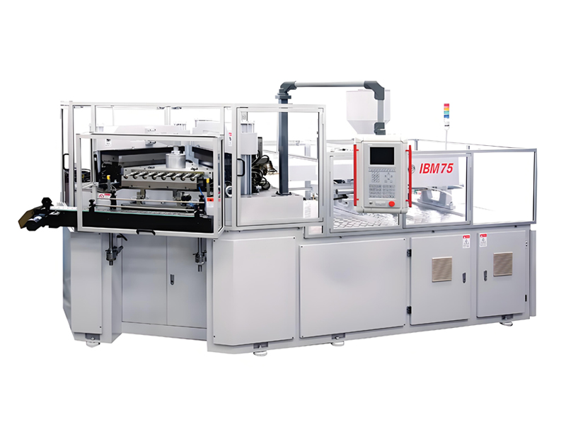
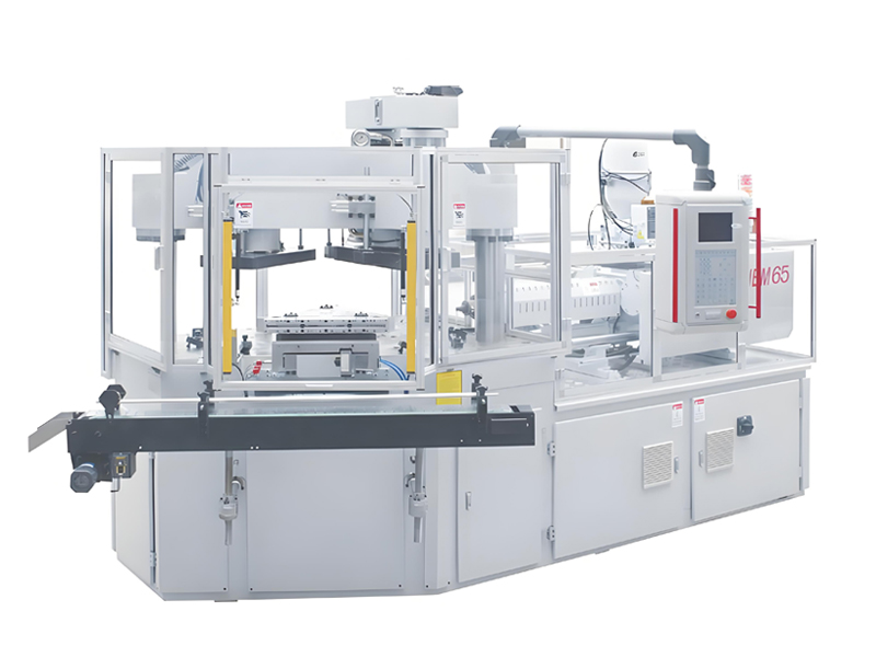
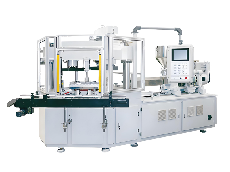
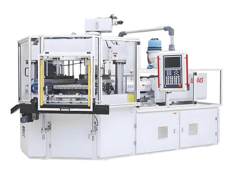
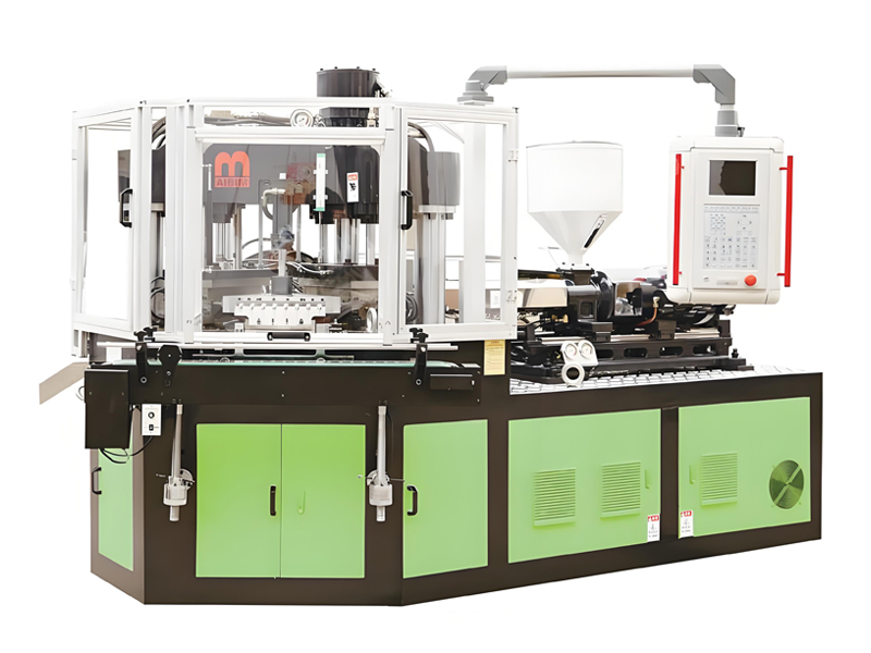
The Aibim I(S)BM range supports exactly this pattern, because the IBM75, IBM65 and IBM55 Hybrid Electric machines share the three-station one-step architecture, the single-crossbeam double-pole clamping framework and the SD card parameter storage system, while differing in clamping capacity, shot capability and drive concept. A plant can therefore add capacity in a different size band without asking its operators to learn a different machine philosophy.
4. Fondamentaux du moulage par injection-soufflage qui guident le cahier des charges
Le choix de la spécification de la deuxième machine exige une compréhension précise de ce que le moulage par injection-soufflage fait différemment des autres voies de formage de corps creux, car ces différences définissent les paramètres qui comptent sur la fiche de commande.
4.1 Le cycle en une étape à trois stations
Dans le processus en une étape à trois stations, une table rotative indexe les tiges noyau à travers trois positions dans une seule machine, sans réchauffage et sans manutention intermédiaire :
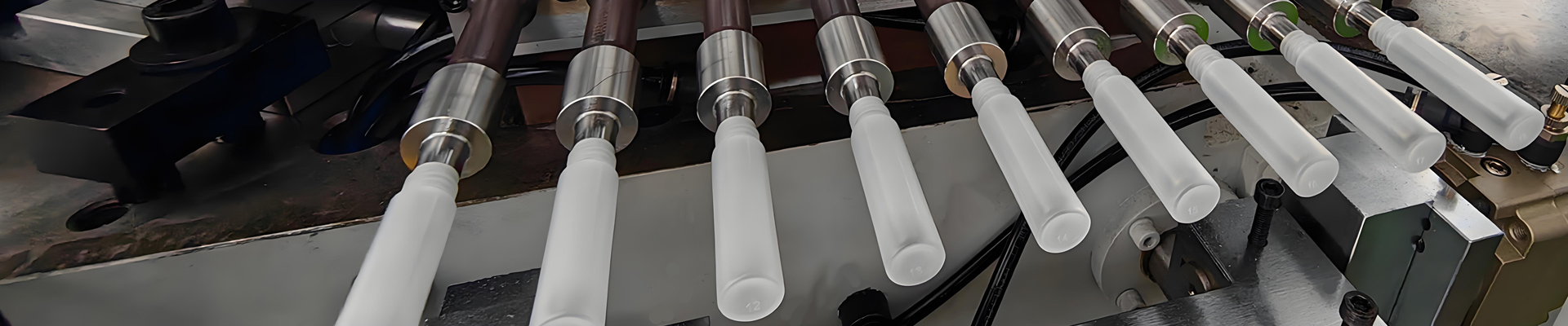
- Station 1 — Injection. Molten resin is injected around a core rod into a preform cavity, forming a parison with a fully finished neck. The neck thread, sealing surface, tamper-evident ring and neck internal diameter are all molded here to injection molding tolerance, typically plus or minus 0.05 mm on critical neck dimensions.
- Station 2 — Blow. The core rod carrying the still-hot parison indexes into the blow mold, where blow air at 0.6 to 1.0 MPa expands the parison against the cavity wall. Body wall thickness is determined by the parison thickness profile designed into the core rod and preform cavity, plus the blow-up ratio.
- Station 3 — Dévêtissage. Le contenant fini est retiré du noyau sur un système de retrait. Sur les machines Aibim, cette station porte un capteur laser numérique longue distance pour la protection du moule, et la zone d’exploitation est protégée par une barrière immatérielle, faisant partie du package de sécurité certifié CE.
Four-station configurations add a dedicated function between blow and strip — most commonly extended cooling, in-mold labeling or leak testing. The fourth station buys cycle time relief when the container wall is thick or the resin has slow crystallization, at the cost of a larger footprint and a more complex index drive.
4.2 Pourquoi IBM plutôt qu'une autre voie de formage de corps creux
Le moulage par injection-soufflage gagne sa place dans l'emballage pharmaceutique, cosmétique et alimentaire des petits contenants pour des raisons à la fois géométriques et économiques.
| Attribute | Injection blow molding (IBM) | Extrusion blow molding (EBM) | Injection stretch blow molding, two-step |
|---|---|---|---|
| Neck finish accuracy | Molded to injection tolerance, typically plus or minus 0.05 mm | Formed by pinch or post-trimming, wider tolerance | Molded to injection tolerance on the preform |
| Flash and trimming | None, no pinch-off and no tail | Pinch-off flash and tail must be trimmed and reground | None on the container |
| Material yield | Very high, typically above 98% with no trim scrap | Lower, 8 to 20% regrind loop depending on part | High |
| Weight consistency | Excellent, controlled by shot volume, plus or minus 1 to 2% | Good, controlled by parison programming | Excellent |
| Typical container volume window | 3 to 1000 mL | 50 mL to several hundred liters | 200 mL to 5 L |
| Handle-ware capability | Not possible | Standard capability | Not possible |
| Tooling investment grade | High, two matched mold sets required | Medium | High, plus separate preform and blow machines |
| Best-fit applications | Pharmaceutical, eye drop, oral liquid, reagent, cosmetic, small food containers | Detergent, lubricant, large containers, handled bottles | Clear beverage bottles, high-volume PET |
The absence of flash is the underrated advantage. It removes the deflashing operation, removes trim scrap from the material balance, removes the regrind loop that many pharmaceutical customers will not accept anyway, and removes an entire family of visual defects from the inspection scope. For a plant producing 10 to 100 mL bottles at hundreds of thousands of pieces per day, that structural difference in material yield compounds far faster than any hourly cycle advantage.
4.3 Les paramètres de spécification qui comptent réellement
Lors de la spécification de la deuxième machine, l'ensemble de paramètres suivant détermine si elle fera le travail que vous prévoyez pour les dix prochaines années. Traitez chaque chiffre comme quelque chose à confirmer par rapport à vos dessins de pièces réels plutôt que comme une abstraction de catalogue.
| Parameter | Typical working range on IBM platforms | What it decides | How to derive it from your parts |
|---|---|---|---|
| Force de serrage | 40 to 200 tons | Maximum projected area of the preform cavity set, therefore maximum cavitation | Projected preform area x cavities x injection pressure factor, plus 15 to 20% safety margin |
| Injection shot capacity | 60 to 800 g | Combined shot weight of all cavities plus runner | Part weight x cavities x 1.25 sprue and safety factor; use 20 to 80% of rated shot |
| Number of cavities | 4 to 24 | Output per cycle and tooling investment grade | Required pieces per hour divided by 3600/cycle; balance against clamp limit |
| Container volume window | 3 to 1000 mL | Product families the cell can serve | List every current and pipeline container; take the extremes |
| Temps de cycle en mode sec | 8 to 25 s | Theoretical output ceiling | Add resin-specific cooling; PP thick wall runs at the slow end |
| Screw diameter and L/D | Sized to shot weight, typically 18 to 24 L/D | Plasticizing rate, melt homogeneity, residence time | Plasticizing rate must exceed shot weight divided by cycle time with 30% margin |
| Mold setting space and daylight | Platform dependent, enlarged on single-crossbeam frames | Whether existing and future tools physically fit | Measure existing mold sets including manifold height and services |
| Blow air pressure | 0.6 to 1.0 MPa | Definition of embossing, base detail and shoulder radius | Thin-wall small containers need the upper range and fast valve response |
| Installed power | Platform dependent; verify against transformer headroom | Electrical infrastructure work required | Sum machine, dryers, chillers, temperature controllers, compressor share |
4.4 Sélection de la résine et son effet sur la spécification de la machine
La résine que la deuxième machine traitera est une donnée de spécification, pas une réflexion après coup. L'indice de fluidité à chaud, le comportement de cristallisation, l'exigence de séchage et la qualité réglementaire influent tous sur la conception de la vis, le contrôle de la température et le temps de cycle.
| Resin | Typical MFR for IBM | Melt temperature range | Mold and core rod temperature | Drying requirement | Typical IBM applications |
|---|---|---|---|---|---|
| PP homopolymer | 8 to 35 g/10 min | 190 to 240 degrees C | Core rod 80 to 130 degrees C, blow mold 8 to 20 degrees C | Not hygroscopic; surface moisture removal only | Pharmaceutical bottles, reagent vials, clear-ish containers |
| PP copolymer | 8 to 25 g/10 min | 190 to 235 degrees C | Core rod 85 to 125 degrees C, blow mold 10 to 20 degrees C | Not hygroscopic | Impact-resistant containers, cold-chain packaging |
| HDPE | 4 to 20 g/10 min | 180 to 230 degrees C | Core rod 60 to 110 degrees C, blow mold 8 to 18 degrees C | Not hygroscopic | Solid dose pharmaceutical bottles, chemical and reagent bottles |
| LDPE / LLDPE | 2 to 20 g/10 min | 170 to 220 degrees C | Core rod 55 to 100 degrees C, blow mold 8 to 15 degrees C | Not hygroscopic | Squeezable dropper bottles, eye drop containers |
| PS | Flow grade dependent | 190 to 240 degrees C | Core rod 60 to 90 degrees C, blow mold 15 to 30 degrees C | Light drying recommended | Clear cosmetic and sample containers |
| PETG / PCTG | Grade dependent | 220 to 255 degrees C | Core rod 70 to 105 degrees C, blow mold 10 to 20 degrees C | Mandatory, dew point minus 30 degrees C or lower | High-clarity cosmetic and personal care bottles |
| PC | Grade dependent | 270 to 310 degrees C | Core rod 90 to 120 degrees C, blow mold 20 to 40 degrees C | Mandatory, 4 hours at 120 degrees C typical | Transparent technical and reusable containers |
Aibim machines process PE (HDPE, LDPE, LLDPE), PP, PS, ABS, SAN, TPU, PC and PCTG, which covers the full practical span of pharmaceutical, cosmetic, food and beverage container work. For medical and pharmaceutical primary packaging, the resin grade must carry the relevant biological and food-contact documentation — USP Class VI and ISO 10993 for medical contact, plus regional food-contact compliance such as EU 10/2011, FDA 21 CFR and GB 4806 — and the machine specification must support the cleanliness and traceability regime that goes with it.
5. Blocs de machines Aibim : IBM75, IBM65 et IBM55 hybride électrique
At this point the plan reaches the practical question: which machine? Aibim, a Wanplas factory, builds three injection blow molding platforms that map cleanly onto the three strategic roles described earlier. All three are three-station, one-step machines covering the 3 to 1000 mL container envelope, all are CE certified, and all share the parameter-portability and safety features that make two-cell operation manageable.
5.1 Bloc produit un : IBM75 — le cheval de trait des volumes
The IBM75 is the platform most often chosen when the second machine is a duplicate or a step-up in a growing pharmaceutical or cosmetic bottle plant. Its clamping framework uses a single crossbeam with double poles, which enlarges the usable mold setting space compared with conventional four-tie-bar layouts of similar tonnage and makes multi-cavity tools with bulky manifolds easier to install and service.
Three design features matter directly to a two-cell operation. The PREFILL hydraulic technology with variable displacement pump pressurizing reduces energy draw during the non-injection portions of the cycle, contributing to the minimum 35 percent energy saving Aibim quotes against conventional hydraulic IBM units. The SD card parameter storage lets a validated process recipe be exported from one machine and loaded into another, which is the single most useful feature when you need machine number two to reproduce machine number one’s process. The stripper station uses a long-distance digital laser sensor for mold protection, and the operating area is guarded by a light curtain.
| IBM75 — configuration reference for capacity planning | Typical specification band | Planning note |
|---|---|---|
| Process architecture | Three-station, one-step injection blow molding | Injection, blow, strip on one indexing table; no preform reheat |
| Container volume range | 3 to 1000 mL across the Aibim I(S)BM range | Confirm the exact band for your tool set on the order drawing |
| Typical cavitation window | 4 to 24 cavities depending on container size | Small droppers at the high end, 500 mL and above at the low end |
| Clamping framework | Single crossbeam, double poles, enlarged mold setting space | Simplifies installation of tall manifold tooling |
| Hydraulic system | PREFILL technology with variable displacement pump pressurizing | Minimum 35% energy saving versus conventional hydraulic IBM units |
| Parameter management | SD card storage, recipe transfer between machines | Key enabler for two-cell process standardization |
| Safety package | CE certified; laser sensor mold protection at stripper station; light curtain | Supports customer and notified-body audits |
| Processable resins | PE (HDPE, LDPE, LLDPE), PP, PS, ABS, SAN, TPU, PC, PCTG | Covers pharmaceutical, cosmetic, food and beverage container work |
| Typical dry cycle window | 8 to 25 s depending on wall thickness and resin | Thin-wall small PE containers at the fast end |
| Best-fit expansion role | Duplicate or step-up | Highest interchangeability with an existing Aibim cell |
5.2 Bloc produit deux : IBM65 et IBM55 hybrides électriques
The IBM65 sits one step below the IBM75 in the range and is frequently chosen when the second machine is intended to specialize in smaller containers — eye drop bottles, oral liquid vials, sample and reagent containers — where high cavitation and short cycles matter more than maximum shot capacity. Because it shares the same three-station architecture and control philosophy, operators move between an IBM65 and an IBM75 with minimal retraining, and process recipes translate conceptually even where the numeric setpoints differ.
The IBM55 Hybrid Electric is the choice when energy consumption per 1000 pieces, cleanroom compatibility and repeatability are the deciding factors. Hybrid electric drive replaces continuously running hydraulic power with servo-electric actuation on selected axes, which reduces idle power draw, lowers heat rejection into the production hall (and therefore the air-conditioning load in a classified cleanroom), reduces hydraulic oil volume and the associated contamination risk, and improves shot-to-shot repeatability because electric injection is less sensitive to oil temperature drift.
| Comparison dimension | IBM75 | IBM65 | IBM55 Hybrid Electric |
|---|---|---|---|
| Platform architecture | Three-station one-step | Three-station one-step | Three-station one-step, hybrid electric drive |
| Position in range | Larger clamp and shot capability | Mid-range clamp and shot capability | Compact, energy and precision focused |
| Typical container focus | Mid to large containers, higher shot weight | Small to mid containers, high cavitation | Small to mid containers, precision and cleanroom work |
| Energy profile per 1000 pieces | Low with PREFILL and variable displacement pump | Low | Lowest in the range; reduced idle draw and heat rejection |
| Shot-to-shot repeatability | High | High | Highest; electric actuation less affected by oil temperature |
| Cleanroom suitability | Good with standard measures | Good with standard measures | Best; lower oil volume and lower heat load |
| Noise level in the hall | Moderate | Moderate | Lower |
| Investment grade | High | Medium to High | High to Premium |
| Best-fit expansion role | Duplicate or step-up for volume growth | Duplicate or complementary for small-container specialization | Complementary for pharmaceutical, cleanroom or energy-driven expansion |
| Parameter portability with existing Aibim cell | Full, via SD card recipe transfer | Full, via SD card recipe transfer | Full on process logic; setpoints re-optimized for electric axes |
6. Moules, interchangeabilité de l'outillage et stratégie de changement de format
Tooling decides whether two machines behave as one flexible resource or as two isolated islands. In injection blow molding the tooling package is intrinsically more complex than in extrusion blow molding, because every container requires a matched pair: a preform cavity and core rod set for the injection station, and a blow cavity set for the blow station, all mounted on a common indexing geometry.
6.1 Le pack d'outillage IBM expliqué
Un ensemble complet d'outillage de moulage par injection-soufflage pour un conteneur comprend :
- Core rods — one per cavity, carrying the parison from injection through blow to strip. They define the internal geometry, the neck internal diameter and, critically, the parison thickness distribution. Core rods are internally temperature-controlled, typically running at 80 to 130 degrees C for PP and 60 to 110 degrees C for HDPE.
- Bloc de cavité de préforme — la cavité d'injection qui forme le profil extérieur de la paraison et la finition complète du goulot, y compris le filetage, la zone de scellage et toute caractéristique inviolable.
- Insertions de bague de goulot — souvent séparables, permettant un changement de filetage sans remplacer tout le bloc de cavité.
- Bloc de cavité de soufflage — la forme du contenant, avec la conception des évents, le gaufrage et la géométrie du fond. Fonctionne à froid, généralement de 8 à 20 degrés C.
- Système de canal chaud ou de collecteur — alimentation équilibrée vers toutes les cavités ; un déséquilibre apparaît immédiatement comme une variation de poids entre les cavités.
- Plaque d'éjection et interface de prélèvement — retire le contenant fini de la tige de noyau sans le rayer.
Tool steel selection follows the resin and the volume commitment. H13 is the standard choice for cavity blocks and core rod bodies in general-purpose PP and PE work. S136 stainless is specified where corrosion resistance and polish retention matter — clear PETG and PS containers, and any tool exposed to humid cleanroom conditions or aggressive cleaning agents. With correct maintenance, a well-built IBM tool set delivers 3 million to 10 million cycles, with the lower end typical of high-cavitation thin-wall tools running abrasive or filled grades and the upper end achievable on well-cooled, unfilled PE and PP work.
| Tooling element | Material and treatment | Contrôle de la température | Typical service life | Two-cell interchangeability note |
|---|---|---|---|---|
| Core rods | H13 or S136, hardened, polished bore | 80 to 130 degrees C for PP; 60 to 110 degrees C for HDPE | 3 to 8 million cycles; tips are consumable | Must match index pitch and clamp geometry of both machines |
| Preform cavity block | H13 for PP/PE, S136 for clear and corrosive grades | Integrated with core rod circuit or separate zone | 5 to 10 million cycles | Interchangeable only within the same clamp and daylight envelope |
| Neck ring inserts | S136 preferred, high polish | Cooled to stabilize thread dimensions | 3 to 6 million cycles | Fully interchangeable if the neck standard is common |
| Blow cavity block | H13, beryllium-free copper alloy inserts for hot spots | 8 to 20 degrees C chilled water | 5 to 10 million cycles | Interchangeable within the same mold setting space |
| Hot runner manifold | Tool steel with balanced flow design | Zone-controlled to melt temperature | Rebuild at 3 to 5 million cycles | Match zone count to both machines’ controller capacity |
| Stripper plate assembly | Hardened steel with wear-resistant guides | Ambient | Wear items replaced annually | Sensor mounting must suit both machines’ protection systems |
6.2 Concevoir l'interchangeabilité dès le départ
Si la deuxième machine est un duplicata, l'interchangeabilité est presque gratuite. S'il s'agit d'une machine de niveau supérieur ou complémentaire, l'interchangeabilité doit être conçue et spécifiée avant la découpe des outils. Quatre décisions régissent le résultat :
- Norme de serrage commune. Spécifiez la même méthode de serrage de moule et la même référence de positionnement sur les deux machines, afin que les outils se montent sans calage et sans réapprendre la position d'index.
- Disposition des services communs. Les positions d'entrée et de sortie d'eau, les raccordements d'air et les types de prises de thermocouple doivent être identiques, avec la même norme de raccord rapide sur les deux cellules. Cela seul peut réduire de 30 à 50 minutes un changement de série.
- Stratégie de plaque adaptatrice. Lorsqu'un outillage plus petit doit fonctionner dans une machine plus grande, concevez un cadre adaptateur permanent plutôt que d'improviser à chaque changement de série. L'adaptateur fait partie de la documentation de l'outillage, et non d'un savoir informel.
- Capacité de zones du contrôleur. Vérifiez que le contrôleur de température de la machine plus petite dispose de suffisamment de zones pour le collecteur de l'outillage plus grand, sinon les outillages « interchangeables » ne sont interchangeables qu'en théorie.
6.3 Le temps de changement de série comme levier de capacité
A plant with more than three changeovers per week per machine has an operational reason to expand, but it also has an opportunity to recover capacity before spending anything. In a two-cell shop, the highest-value tooling strategy is often specialization: dedicate one cell to the two or three highest-volume, longest-running products and let the other absorb the fragmented short-run work.
The arithmetic is straightforward. A plant running 3.5 changeovers per week at 4.5 hours each loses 15.75 hours per week per machine, which is roughly 7 to 9 percent of available time on a two-shift schedule. After specialization, the high-volume cell may drop to 0.5 changeovers per week (2.25 hours) while the flexible cell rises to 6 (27 hours). Total changeover time increases in absolute terms, but it is now concentrated on the cell whose schedule can absorb it, and the high-volume cell gains almost 14 hours of productive time per week without any hardware change.
Reduce the changeover itself in parallel. Preheating core rods and manifolds offline before the tool goes into the machine, pre-kitting all fasteners and couplers, standardizing on quick couplers, using the SD card to load the target recipe before the mechanical work is finished, and running a documented first-article sequence typically cuts an unstructured 5-hour changeover to 2.5 to 3.5 hours.
7. Services publics et infrastructure d'usine pour un atelier à deux cellules
The second injection blow molding machine is never just a machine. Every supporting utility that was adequately sized for one cell now faces roughly double the load, and the failure mode is insidious: nothing breaks, but both cells drift out of their validated process window simultaneously whenever peak demand coincides. Utilities work should be completed and commissioned before the machine arrives, not in parallel with it.
7.1 Capacité électrique et marge du transformateur
Sum the installed power of everything the expansion adds: the machine itself, the resin dryer and central feeding system, the additional mold temperature controllers (2 to 4 units per cell, covering core rod heating and blow mold chilling circuits), the incremental chiller load, the incremental compressor load, plus takeout conveyors and any inspection equipment.
Règles de conception qui préviennent systématiquement les problèmes :
- Conservez 25 à 30 pour cent de capacité de transformateur de réserve après le chargement complet de la deuxième cellule. Les machines prélèvent un courant de pointe pendant la plastification et la fermeture simultanées, et deux cellules se synchronisent parfois.
- Dimensionnez le câblage pour la charge continue plus la surtension de démarrage, et vérifiez la chute de tension à la machine la plus éloignée lors d'un démarrage simultané dans le pire des cas.
- Installez un comptage séparé par cellule. Sans données énergétiques par machine, le kWh pour 1000 pièces ne peut pas être mesuré, et l'avantage énergétique d'une machine hybride électrique ou équipée PREFILL ne peut pas être prouvé à la direction.
- Vérifiez le facteur de puissance. Ajouter une deuxième machine hydraulique à une usine déjà proche du seuil de facteur de puissance du service public peut déclencher des pénalités entièrement évitables avec un équipement de correction.
- Vérifiez que le système de mise à la terre et de liaison, les circuits d'arrêt d'urgence et les verrouillages du rideau de lumière sont intégrés dans l'architecture de sécurité de l'usine plutôt qu'isolés au niveau de la machine.
7.2 Refroidissement : puissance du refroidisseur, capacité de la tour et circuits d'eau
C'est au niveau du refroidissement que la plupart des expansions à deux cellules échouent réellement. Le moulage par injection-soufflage nécessite deux circuits thermiques distincts à la fois — des circuits chauds pour les tiges de noyau et les cavités de préforme, des circuits glacés pour les moules de soufflage — et ils doivent être indépendamment stables.
Utilisez environ 0,25 à 0,3 tonne de réfrigération par kW installé de capacité de machine comme règle de dimensionnement de première passe, puis affinez en fonction du rejet de chaleur réel du débit de résine. Vérifiez spécifiquement ces points :
- Chilled water temperature stability. Blow molds want 8 to 20 degrees C with a variation no greater than plus or minus 1 degree C. A chiller that holds this under single-cell load can oscillate by 3 to 6 degrees C once a second cell cycles asynchronously, and every degree of drift moves shrinkage and wall thickness.
- Débit et diamètre des tuyaux. Les collecteurs sous-dimensionnés sont la contrainte cachée classique. Calculez le débit requis en mètres cubes par heure pour les deux cellules au pic, puis dimensionnez le collecteur principal pour ce total plus 20 pour cent, et non pour la somme de deux tuyaux de dérivation.
- Isolation des circuits. Chaque cellule doit être équipée de vannes d'isolement et de ses propres manomètres et thermomètres afin qu'une machine puisse être entretenue sans arrêter l'autre. Sans isolation, la redondance est perdue.
- Tour de refroidissement et évacuation de la chaleur. Vérifiez que la tour et le traitement de l'air de l'usine peuvent évacuer la chaleur supplémentaire au cours du mois le plus chaud, et non la moyenne annuelle. Les zones de salle blanche doivent également être vérifiées par rapport à la charge de climatisation.
- Qualité de l'eau. L'entartrage et le biofilm réduisent le transfert de chaleur dans les canaux étroits des tiges noyau plus rapidement que dans toute autre partie du système. Ajoutez une filtration et un régime de traitement lorsque la deuxième cellule double le volume en circulation.
7.3 Air comprimé
L'air de soufflage à 0,6 à 1,0 MPa est une variable de processus, et non un service. La chute de pression pendant la phase de soufflage produit une mauvaise définition du gaufrage, des épaules molles et un détail de base incohérent — des défauts facilement mal diagnostiqués comme des défauts d'outillage.
- Calculez la consommation en mètres cubes par minute par cellule à partir du volume de soufflage, de la cavitation et du taux de cycle, puis ajoutez les pertes de vannes et de lignes.
- Installez un réservoir dimensionné pour que la chute de pression lors d'un soufflage simultané sur les deux cellules reste à moins de 0,05 MPa du point de consigne.
- Développez le sécheur réfrigéré et la filtration en parallèle du compresseur. L'humidité dans l'air de soufflage provoque des taches et, dans le travail pharmaceutique, est une constatation de contamination lors d'un audit.
- Envisagez un circuit haute pression dédié pour l'air de soufflage, séparé de l'air général de l'atelier utilisé pour la pneumatique et le nettoyage, afin que la demande d'air de l'atelier ne puisse pas perturber le processus.
7.4 Le tableau complet de dimensionnement des utilités
| Utility or system | Sizing rule for the second cell | Typical failure if under-sized | Lead time to expand | Investment grade |
|---|---|---|---|---|
| Transformer and main distribution | Retain 25 to 30% headroom after full dual-cell load | Breaker trips on simultaneous peak; voltage sag; cycle instability | Longest item; start first | Medium to High |
| Chilled water plant | 0.25 to 0.3 refrigeration tons per installed kW; hold plus or minus 1 degree C | Blow mold temperature drift, shrinkage and wall thickness variation | Medium | Medium to High |
| Cooling tower and heat rejection | Verify against hottest-month ambient, not annual average | Chiller condensing pressure rises, capacity falls in summer | Medium | Medium |
| Cooling water headers and pumps | Total peak flow in cubic meters per hour plus 20%; isolating valves per cell | Second cell starves the first; no ability to service one machine alone | Short, but disruptive to install | Low to Medium |
| Mold temperature controllers | 2 to 4 units per cell: core rod 80 to 130 degrees C, blow mold 8 to 20 degrees C | Slow warm-up, unstable neck dimensions, extended startup scrap | Short | Low |
| Compressed air, blow circuit | 0.6 to 1.0 MPa; receiver sized to hold within 0.05 MPa on simultaneous blow | Poor embossing, soft shoulders, inconsistent base detail | Short to Medium | Medium |
| Air dryer and filtration | Expand with the compressor; dew point suited to cleanroom class | Water spotting, contamination findings in audits | Short | Low |
| Resin drying and central feeding | Throughput for both cells plus one changeover buffer; separate loops per resin | Cross-contamination, moisture defects in PETG and PC work | Medium | Medium |
| Granulator and regrind loop | Beside-the-press unit per cell; closed loop with documented regrind ratio | Uncontrolled regrind, traceability failure in pharmaceutical audits | Short | Low |
| Cleanroom air handling | Recalculate air changes for the added heat and personnel load | Class excursions, particle count failures during peak production | Long | High |
| Compressed air and water metering | Per-cell metering for kWh, cubic meters per hour and cubic meters per minute | No baseline for energy per 1000 pieces; improvements unprovable | Short | Low |
8. Implantation, classe de salle blanche et manutention des matériaux
L’emplacement de la deuxième machine détermine l’efficacité de la maintenance, le flux de matériaux et le contrôle de la contamination pendant des années. Les erreurs d’agencement sont les plus difficiles à corriger : une fois les services auxiliaires enterrés et la cloison de la salle blanche construite, déplacer une machine de deux mètres devient un projet en soi.
8.1 Règles d'espace et d'accès
- Emprise au sol de la machine plus enveloppe de service. Prévoyez l'emprise au sol de la machine en mètres carrés plus une enveloppe de service autour de celle-ci. Une machine qui s'insère exactement dans son marquage au sol ne peut pas être entretenue.
- Allée de maintenance d'au moins 1,2 m du côté opérateur et derrière la machine, assez large pour un chariot à moules, une boîte à outils et un technicien travaillant simultanément.
- Accès au changement de moule. Confirmez que le chemin de la grue ou du palier atteint la zone de moule des deux machines. Vérifiez la capacité de levage par rapport à l'ensemble d'outils le plus lourd, y compris le collecteur, pas l'outil moyen.
- Hauteur de plafond et dégagement de la grue. Vérifiez la hauteur libre sous le crochet, en tenant compte de l'outil le plus haut plus l'élingage plus la marge de sécurité.
- Zone de stockage des moules. En rayon, étiquetée, climatisée si possible, avec un emplacement défini par outil. Un atelier à deux cellules double généralement le nombre d'outils en rotation en deux ans.
- Flux des granulés et des produits finis. Concevez un flux à sens unique, de la réception de la résine en passant par le séchage et le moulage jusqu'à l'inspection, l'emballage et l'expédition. Les flux croisés sont un risque de contamination et une constatation d'audit dans le travail pharmaceutique.
- Charge et nivellement du sol. Vérifiez l'épaisseur de la dalle et la capacité de charge pour les charges statiques et dynamiques de la machine, en particulier dans les bâtiments anciens ou aux étages supérieurs.
8.2 Décisions de classification des salles blanches
Whether the second cell needs to sit inside a classified area depends entirely on the end product and the customer’s quality agreement. Pharmaceutical primary packaging typically requires a controlled environment equivalent to ISO 14644 Class 8 (often described as 100,000 class, or D-grade in some pharmaceutical frameworks) at the point of container formation and packing. Food and cosmetic work more often requires a controlled but unclassified area with defined hygiene practices.
Il existe trois approches pratiques, et le choix affecte à la fois les travaux de construction et la spécification de la machine :
- Classification complète de la salle. L'ensemble du hall de moulage est classifié. Plus haut niveau d'investissement, le plus simple opérationnellement, la plus haute consommation d'énergie de traitement d'air.
- Enceinte localisée au-dessus de la zone de décharge. L'air propre n'est délivré qu'au-dessus de la station d'éjection, de la zone de sortie et de l'emballage. Niveau d'investissement moyen, très courant en pratique, et il fonctionne bien car les contenants IBM ne sont scellés à l'ambiance qu'après avoir quitté le noyau.
- Segregated cleanroom cell. The second machine is installed inside a partitioned classified room while the first stays in the general hall. This is the natural choice when the second machine is complementary and specifically targets pharmaceutical work — and it is where a hybrid electric machine earns its premium, because lower heat rejection and reduced hydraulic oil volume directly reduce the air handling load and contamination risk.
Quelle que soit la voie que vous choisissez, planifiez dès le départ les sas pour le personnel et les matériaux, la discipline d’habillage, la surveillance de la pression différentielle et un calendrier de surveillance du comptage des particules. L’ajout d’un sas dans un agencement déjà terminé est beaucoup plus perturbant que de le prévoir sur le plan.
9. Effectifs, modèles d'équipes et courbe de montée en cadence
La capacité est fournie par les personnes qui exploitent les machines, et le modèle de main-d’œuvre pour deux cellules n’est pas simplement le double de celui d’une seule. Certains rôles évoluent de manière linéaire, certains à la moitié du rythme, et un — l’ingénieur de processus — doit souvent être créé pour la première fois lorsque la deuxième machine arrive.
9.1 Modèle d'effectif pour deux cellules
Sur une cellule mature de moulage par injection-soufflage produisant un produit stable, un opérateur peut superviser une à deux machines, à condition que le retrait et le conditionnement soient partiellement automatisés et que les machines utilisent un outillage éprouvé. Pendant la montée en cadence, prévoyez un opérateur par machine quel que soit l’objectif final.
| Role | One cell, two shifts | Two cells, two shifts | Two cells, three shifts | Scaling behavior |
|---|---|---|---|---|
| Machine operator | 2 | 2 to 4 | 3 to 6 | Sub-linear once both cells run proven tooling |
| Packing and visual inspection | 2 to 4 | 4 to 7 | 6 to 10 | Near-linear; the main variable is automation level |
| Mold technician | 1 | 1 to 2 | 2 | Driven by changeover frequency, not machine count |
| Process engineer | Shared or part-time | 1 dedicated | 1 to 2 | Step change; two cells need process standardization ownership |
| Maintenance technician | Shared | 1 | 1 to 2 | Step change; preventive maintenance can no longer be improvised |
| Quality inspector | 1 | 1 to 2 | 2 to 3 | Driven by sampling plan and regulatory class, not machine count |
| Shift supervisor | Shared with production manager | 1 per shift | 1 per shift | Step change at two cells |
Track labor productivity in man-hours per 1000 pieces rather than headcount. A single cell running 16 cavities at a 11.5-second cycle with two operators and two packers produces roughly 5,000 pieces per hour with four people present, which is about 0.8 man-hours per 1000 pieces. A well-run two-cell shop should reach 0.55 to 0.65 man-hours per 1000 pieces once shared roles absorb the second machine — and that improvement in labor intensity is one of the strongest and most defensible arguments for the expansion, entirely independent of any price assumption.
9.2 La courbe de montée en cadence, semaine par semaine
Planifiez la montée en cadence comme un projet défini avec des jalons, et non comme « on démarre et on verra ». Le calendrier suivant reflète une machine de duplication ou de montée en puissance installée dans une usine de bouteilles existante avec des services déjà préparés.
| Phase | Duration | Key activities | Expected yield | Exit gate |
|---|---|---|---|---|
| Pre-arrival preparation | 4 to 8 weeks before delivery | Transformer and chiller work, foundation and floor marking, header piping, air receiver, mold storage racks, SOP drafting | n/a | Utilities commissioned and metered; site readiness checklist signed |
| Delivery and positioning | 3 to 7 days | Offloading, positioning, leveling, anchoring, service connections | n/a | Machine level within tolerance; all services connected and pressure tested |
| Installation and commissioning | 2 to 4 weeks | Power-up, hydraulic and electrical checks, safety circuit and light curtain verification, dry cycle running, first tool installation, engineer-supervised startup | First parts only | Dry cycle within specification; safety verification complete; first acceptable containers produced |
| Trial production | 2 to 3 weeks | Process window development, cavity balance, weight and wall thickness mapping, cycle optimization, first-article approval, operator training on the live cell | 85% rising to 93% | Cpk of critical dimensions at or above 1.33; first article approved |
| Qualified production | 2 to 4 weeks | Continuous running on one or two proven tools, SPC established, changeover procedure validated, preventive maintenance schedule started | 93% rising to 97% | Three consecutive shifts at target rate and yield |
| Full mix and stable output | 2 to 4 weeks | Remaining tools introduced, scheduling rules between the two cells finalized, energy per 1000 pieces baselined | 97% and above | Cell OEE within 5 points of the established cell |
| Cumulative to design capacity | 8 to 14 weeks from arrival | Full production planning integration | 97 to 99% | Two-cell shop delivering 70 to 80% net effective gain, trending upward |
9.3 Transférer les connaissances du procédé à la deuxième cellule
Le plus grand risque dans un atelier à deux cellules est que les deux machines développent deux processus différents pour la même pièce. Empêchez-le structurellement plutôt que par la supervision.
Digitize the existing cell’s accumulated experience before the new machine arrives. Build a process parameter library — one record per tool, capturing melt profile by zone, injection pressure and speed profile, hold pressure and time, back pressure, screw speed, core rod and blow mold temperature setpoints, blow pressure and timing, cycle breakdown, validated weight window and known defect countermeasures. The SD card parameter storage on Aibim machines makes this library directly actionable: an approved recipe can be exported from the established machine and loaded into the new one, so the second cell starts from a proven baseline instead of an operator’s memory.
Training for the second cell is deliberately kept lean here, because it belongs to a different discipline. In this scaling plan, treat it as three concrete deliverables: a written SOP set transferred and adapted from the established cell, a supervised run-in period where each operator completes a defined number of shifts alongside the commissioning engineer, and a sign-off checklist covering safety interlocks, changeover, startup and shutdown, defect recognition and escalation. Anything deeper — structured skill matrices, certification levels and long-term competency development — is a separate program and should not be allowed to delay the ramp-up gate.
10. Indice d'investissement, modélisation du TRS et retour sur investissement en mois
Comparing expansion options requires a common financial language that does not depend on any currency, region or quotation. The indexed model below does exactly that: it sets a baseline single IBM75 cell at 100 points and expresses every other option as a relative index, with recovery expressed as a payback window in months at a stated OEE.
10.1 Définir l'indice d'investissement pour l'expansion de la capacité
The capacity expansion investment index counts everything the expansion requires, not just the machine. Baseline definition: one IBM75 cell, one standard multi-cavity tool set, the incremental utility work for a second cell in a prepared building, installation and commissioning, and initial spare parts — together equal to 100 points.
| Expansion option | Machine index points | Tooling index points | Utilities and building index points | Total index (baseline = 100) | Nominal capacity gain | Payback window at 78% OEE, two shifts |
|---|---|---|---|---|---|---|
| Baseline: duplicate IBM75 cell with existing tooling reused | 58 | 18 | 24 | 100 | Plus 85 to 95% | 16 to 26 months |
| Duplicate cell with a full new tool set | 58 | 34 | 24 | 116 | Plus 85 to 95% | 19 to 30 months |
| Step-up to a larger clamp with higher cavitation | 72 | 40 | 31 | 143 | Plus 110 to 130% in piece terms | 20 to 32 months |
| Complementary hybrid electric cell in a classified area | 78 | 36 | 52 | 166 | Plus 70 to 85%, plus new market access | 24 to 38 months |
| Third shift on the existing cell only | 0 | 0 | 6 | 6 | Plus 35 to 45% | Immediate, but labor grade High and OEE falls 4 to 8 points |
| Continued subcontracting | 0 | 0 | 0 | 0 | Variable | No asset created; margin leakage grade High |
| Automation retrofit on the existing cell before expanding | 0 | 4 | 14 | 18 | Plus 8 to 15% via OEE recovery | 10 to 18 months |
Read the last row carefully. Recovering 8 to 15 percent of capacity through automation and OEE work costs about 18 index points against 100 for a full second cell, and it pays back faster. That is why the trigger scorecard in section 1 comes first: if OEE is below 78 percent, the cheapest capacity in the plant is still inside the machine you already own.
10.2 Sensibilité du retour sur investissement à l'OEE et au régime d'équipes
Les mois de retour sur investissement ne sont pas une propriété de la machine ; ils sont une propriété de la façon dont vous la faites fonctionner. Le tableau ci-dessous montre comment la même cellule dupliquée de référence se comporte sous différentes hypothèses d'exploitation.
| Scenario | Shift pattern | Achieved OEE | Effective annual output index | Payback window | Comment |
|---|---|---|---|---|---|
| Conservative | Two shifts, 5 days | 70% | 100 | 26 to 34 months | Ramp-up problems unresolved; changeovers not optimized |
| Planning base case | Two shifts, 6 days | 78% | 134 | 16 to 26 months | The realistic default for a well-managed second cell |
| Strong execution | Two shifts, 6 days | 85% | 146 | 14 to 22 months | Specialized cells, low changeover frequency |
| Three-shift continuous | Three shifts, 6 days | 80% | 206 | 11 to 17 months | Requires full night-shift staffing and maintenance discipline |
| Underloaded | One shift, 5 days | 75% | 54 | Above 40 months | Second cell bought ahead of demand; avoid unless redundancy is the objective |
10.3 Références de consommation unitaire qui pilotent le modèle
Le côté opérationnel du modèle doit être suivi en unités physiques pour 1000 pièces, qui sont sans monnaie, comparables entre les usines et directement exploitables.
| Unit metric | Conventional hydraulic IBM unit | Modern PREFILL hydraulic cell | Hybrid electric cell | How to improve it |
|---|---|---|---|---|
| Energy, kWh per 1000 pieces (30 mL PP bottle, 16 cavities) | Baseline | Approximately 35% lower than conventional hydraulic units | Lowest in the range; further reduction in idle and standby draw | Variable displacement pumping, insulated barrel jackets, optimized cooling setpoints |
| Labor, man-hours per 1000 pieces | 0.8 to 1.1 | 0.6 to 0.85 | 0.55 to 0.8 | Automated takeout, one operator covering two cells, in-line inspection |
| Scrap rate, percent | 3 to 6% | 1.5 to 3% | 1 to 2.5% | SPC, stable core rod temperature, cavity balance, startup scrap reduction |
| Startup scrap per changeover, pieces | High | Medium | Low to Medium | Recipe recall via SD card, offline preheating, documented first-article sequence |
| Cooling water, cubic meters per hour per cell | Higher, poorer circuit control | Optimized with zoned circuits | Lowest; less hydraulic heat to reject | Circuit isolation, flow balancing, scale control |
| Compressed air, cubic meters per minute per cell | Baseline | Baseline with better valve response | Baseline; blow air demand is process-driven | Leak elimination, correct receiver sizing, dedicated blow circuit |
| Maintenance hours per 1000 running hours | Higher; more hydraulic service | Medium | Lower on hydraulic items, higher on servo diagnostics | Preventive schedule, oil analysis, spare parts availability |
11. Registre des risques, pièces de rechange et constance de la qualité
Chaque projet d'extension porte trois familles de risques : le risque de demande (les commandes ne se matérialisent pas), le risque de qualité (deux machines produisent deux produits différents) et le risque de chaîne d'approvisionnement (une pièce d'usure arrête la ligne). Chacun a une couverture spécifique et ingénierable.
11.1 Risque de demande et engagement par phases
The hedge against demand uncertainty is optionality built into the specification. Choose a machine and tooling package that can serve more than one product family; a cell locked to a single container geometry becomes a liability the moment that program softens. Prefer configurations where the clamp and shot capacity comfortably cover the pipeline’s second and third products, not only the anchor product.
Phase the commitment. Install the machine with the anchor tool set first and defer the secondary tools until the anchor program stabilizes, which spreads the tooling index points across quarters. Where redundancy for existing customers is part of the justification, make sure at least one high-volume existing tool is qualified on the new cell during ramp-up, so the redundancy benefit is real and auditable rather than theoretical.
11.2 Régularité de la qualité entre deux cellules
Les clients n'acceptent pas que « la machine deux fonctionne légèrement différemment ». Normalisez délibérément :
- Un standard de paramètres par outil, stocké centralement et chargé via carte SD, avec des décalages spécifiques à la machine documentés et approuvés plutôt qu'improvisés.
- Approbation de la première pièce sur les deux machines pour chaque outil, et non seulement sur la machine où l'outil a été développé.
- SPC avec un Cpk égal ou supérieur à 1,33 sur les dimensions critiques — diamètre interne du col, profil du filetage, planéité de la surface d'étanchéité, hauteur totale, poids du contenant et épaisseur minimale de paroi. Les clients pharmaceutiques demandent fréquemment 1,33 comme plancher et 1,67 sur les caractéristiques critiques pour la sécurité.
- Traçabilité au niveau de la cavité. Marquez les numéros de cavité sur la base du contenant afin qu'une dérive dimensionnelle puisse être attribuée à une cavité plutôt qu'à la machine.
- Audit inter-machines une fois par trimestre : faites fonctionner le même outillage sur les deux cellules et comparez la répartition du poids, la cartographie de l'épaisseur de paroi et les dimensions du col. Une divergence au-dessus du seuil convenu déclenche une enquête avant qu'un client ne la découvre.
- Méthode de mesure commune. Les deux cellules doivent utiliser les mêmes jauges, le même plan d'échantillonnage et la même procédure de mesure, sinon les différences apparentes sont des artefacts métrologiques.
11.3 Stratégie des pièces de rechange et liste des pièces d'usure
A two-cell shop needs a spare parts policy, not a spare parts drawer. The rule is simple: any part whose failure stops production and whose replenishment lead time exceeds the tolerable downtime must be held in stock. Commonality between the two machines is what makes this affordable — one set of critical spares can cover both cells when the machines share a platform.
| Wear or spare part | Function | Typical replacement interval | Stock policy for a two-cell shop | Downtime if unavailable |
|---|---|---|---|---|
| Screw tip and non-return valve assembly | Controls melt cushion and shot repeatability | 8,000 to 15,000 running hours | One complete set held; inspect at every major service | Very High; weight control lost, production stops |
| Barrel heater bands and thermocouples | Melt temperature zones | 12 to 24 months per zone | Two of each size and type per machine | High; one failed zone can halt processing |
| Nozzle tip and nozzle heater | Melt delivery to the manifold | 12 to 18 months | One spare of each | High; drooling and stringing defects |
| Hydraulic seals and O-ring kits | Clamp and injection hydraulic cylinder sealing | Annual inspection; 2 to 3 years replacement | Full kit per machine platform | Medium to High; leaks and pressure loss |
| Hydraulic oil filters | Contamination control | 1,500 to 3,000 running hours | Minimum six months of consumption | Medium; accelerated pump and valve wear |
| Core rod tips and sealing inserts | Parison formation and neck sealing | Tool dependent; 1 to 3 million cycles | One full set per active high-volume tool | Very High; one damaged rod scraps that cavity |
| Blow air valves and seals | Blow pressure and timing control | 12 to 24 months | Two valve assemblies | High; inconsistent blow and dimensional drift |
| Quick couplers and cooling hoses | Tool services | 12 to 18 months | Generous stock; low value, frequent failure | Medium; leaks during changeover |
| Laser sensor and light curtain spares | Mold protection and personnel safety | On failure | One of each safety-critical device | Very High; safety devices cannot be bypassed |
| Temperature controller modules | Core rod and blow mold circuits | On failure | One spare module per controller type | Medium to High; startup delays and scrap |
| Drive belts, pump couplings | Power transmission | 18 to 36 months | One set per machine | Medium |
The Wanplas group policy of USD 500 free parts every year, applied to each machine, is designed to cover exactly this class of consumable wear items. In a two-cell shop the entitlement applies per machine, which means the annual consumable budget for filters, heater bands, seals and couplers is largely absorbed for both cells — provided you plan the annual parts list in advance rather than ordering reactively after a stoppage.
11.4 Le registre consolidé des risques
| Risk | Early warning indicator | Impact grade | Hedge |
|---|---|---|---|
| Anchor program volume falls short | Rolling forecast revised down two months running | High | Choose a flexible clamp and shot envelope; phase tooling; qualify a second product family early |
| Quality divergence between cells | Weight or dimension drift on cross-machine audit | High | Central recipe library, SPC with Cpk at or above 1.33, cavity-level traceability |
| Utility shortfall under dual load | Chilled water temperature swing above plus or minus 1 degree C | Very High | Complete and commission utilities before machine arrival; per-cell isolation valves |
| Ramp-up slower than planned | Yield stuck below 93% after trial production gate | Medium | Engineer-supervised commissioning, parameter transfer, defined ramp gates |
| Wear part unavailable | Stock-out on any item in the critical list | High | Safety stock policy, annual parts plan against the USD 500 free parts entitlement |
| Skilled labor shortage on the new shift | Recruitment cycle exceeding six weeks | Medium | Start recruitment before delivery; cross-train existing staff; supervised run-in |
| Customer audit finding on the new cell | Gaps in validation or cleanroom documentation | High | Document commissioning, safety verification and validation batches as they happen |
| Tooling delivery later than machine | Tool trial dates slipping at the mold maker | Medium to High | Order tooling in parallel with the machine; keep one proven tool available for commissioning |
12. Applications, secteurs et paysage de certification
The second machine should be specified against the industries you serve today and the two you intend to enter next. Aibim machines are built for four application fields — pharmaceutics, food, drink and cosmetics — and each imposes a different combination of container geometry, resin, tolerance and regulatory documentation.
12.1 Emballage pharmaceutique et médical
This is the natural home of injection blow molding, because the molded neck finish delivers the sealing accuracy that closure integrity depends on. Typical products include solid dose tablet bottles in HDPE from 30 to 500 mL, oral liquid bottles in PP from 30 to 200 mL, eye drop containers in LDPE from 5 to 15 mL, dropper and nasal spray bottles, reagent and diagnostic vials from 3 to 50 mL, and effervescent tablet tubes.
Requirements that must appear in the machine and plant specification: resin grades documented for pharmaceutical contact, with USP Class VI and ISO 10993 biological evaluation where the product contacts the body; ISO 15378 as the GMP framework for primary packaging materials; a controlled environment at the discharge and packing zone; full batch traceability including resin lot, machine, tool, cavity and shift; and validated cleaning and changeover procedures. Neck dimensional capability is the single most audited characteristic, which is why Cpk at or above 1.33 on neck internal diameter and thread profile should be designed into the process from the first trial.
12.2 Cosmétiques et soins personnels
Cosmetic work rewards surface quality and geometric freedom: cream jars, serum and essence bottles from 15 to 150 mL, lotion bottles up to 500 mL, sample and travel sizes from 3 to 30 mL, roll-on containers and deodorant bodies. Clarity-critical work in PETG, PCTG or PS demands S136 tooling with high polish, tight blow mold temperature control and careful venting to avoid haze and flow marks.
Cosmetic customers change designs more often than pharmaceutical customers, which puts changeover frequency at the center of the capacity plan. This is precisely the segment where a two-cell shop with one specialized high-volume cell and one flexible short-run cell outperforms a single machine forced to do both.
12.3 Contenants pour aliments et boissons
Small-volume food and drink containers — spice and seasoning bottles, sauce and condiment containers, honey and syrup bottles, dairy and probiotic drink bottles from 50 to 250 mL, and nutraceutical and supplement bottles — combine food-contact compliance with high-volume economics. Relevant frameworks include EU 10/2011 for plastic materials in contact with food, FDA 21 CFR for the United States market, and GB 4806 for the Chinese market. Where the container is filled hot or pasteurized, resin selection shifts toward PP grades with higher heat resistance, and blow mold temperature control becomes more demanding.
12.4 Liste de contrôle de certification et de conformité pour l'usine agrandie
| Standard or framework | Scope | Applies to | What the second cell must demonstrate |
|---|---|---|---|
| ISO 9001 | Quality management system | All production | New cell integrated into document control, calibration, training records and internal audit scope |
| ISO 15378 | GMP for primary packaging materials for medicinal products | Pharmaceutical containers | Validation of the new cell, change control, contamination control, full traceability |
| ISO 14644 | Cleanroom classification | Classified production areas | Particle counts, air changes and pressure differentials verified with the new machine running |
| EU 10/2011 | Plastic materials in contact with food | Food, drink and many cosmetic containers | Compliant resin grades, declaration of compliance, migration considerations |
| FDA 21 CFR | Food-contact substances, United States | Food and drink containers | Compliant resin and additive selection, documented supply chain |
| GB 4806 | Food-contact materials, China | Food and drink containers | Compliant resin grades and testing documentation |
| USP Class VI | Biological reactivity of plastics | Pharmaceutical and medical contact | Documented resin grade with valid certification |
| ISO 10993 | Biological evaluation of medical devices | Medical-contact containers and components | Evaluation appropriate to contact type and duration |
| CE marking | Machinery safety in the European market | The machine itself | Aibim machines are CE certified; verify the safety configuration matches the installed layout |
13. Guide de sélection : du besoin au modèle
Le tableau suivant convertit les scénarios d'expansion courants en une recommandation de départ concrète de la gamme I(S)BM d'Aibim. Traitez-le comme un premier filtre ; la configuration finale suit toujours un examen de vos plans de pièces, de la résine, de l'objectif de cavitation et de l'exigence de cycle.
| Your situation | Container size and material | Output requirement | Recommended Aibim model | Suggested configuration notes |
|---|---|---|---|---|
| Volume growth in one pharmaceutical bottle family; existing Aibim cell at high OEE | 30 to 200 mL PP or HDPE | 2 to 4 million pieces per month | IBM75 as a duplicate | Match clamp, control platform and clamping standard to the existing cell; reuse proven tooling |
| Enquiries repeatedly exceed the current volume ceiling | 250 to 1000 mL PP, HDPE or PETG | 1 to 2.5 million pieces per month | IBM75 as a step-up | Specify enlarged mold setting space and shot capacity for the heaviest planned part plus 25% |
| Small-container specialization; high cavitation, short cycles | 3 to 60 mL LDPE, PP or PS | 3 to 6 million pieces per month | IBM65 | High cavity count, optimized cooling, automated takeout to hold man-hours per 1000 pieces low |
| Pharmaceutical program requiring a classified area | 5 to 100 mL PP, HDPE or LDPE | 1 to 3 million pieces per month | IBM55 Hybrid Electric | Segregated cleanroom cell; lower heat rejection reduces air handling load; ISO 15378 documentation from day one |
| Energy consumption per 1000 pieces is the deciding metric | 10 to 250 mL PP or PE | 1.5 to 3 million pieces per month | IBM55 Hybrid Electric | Per-cell metering from commissioning to prove the improvement against the existing cell |
| High-clarity cosmetic containers, frequent design changes | 15 to 150 mL PETG, PCTG or PS | 0.8 to 2 million pieces per month | IBM65 or IBM75 depending on shot weight | S136 tooling, dew point drying below minus 30 degrees C, fast changeover package |
| Redundancy and business continuity are the main driver | Same as existing production | Match existing cell | Duplicate of the existing Aibim model | Qualify at least two high-volume tools on both cells during ramp-up |
| Mixed portfolio, more than three changeovers per week | 3 to 500 mL, multiple resins | Fragmented, many short runs | IBM65 or IBM75 as the flexible cell | Dedicate the existing cell to long runs; specify quick-change tooling on the new machine |
14. Service, mise en service et assistance
Les conditions commerciales autour d'une seconde machine comptent plus que celles de la première, car la montée en cadence de la seconde machine se déroule pendant que la première livre encore aux clients. Il n'y a pas de période calme pour absorber les problèmes.
14.1 Avant l'expédition
Aibim manufactures machine parts in its own CNC center, which keeps dimensional consistency of critical components under direct control and shortens the loop when a part needs to be reworked or replaced. Before shipment, request a documented functional test with your own tooling where possible, verification of dry cycle time against the specification, confirmation of the safety configuration including the stripper station laser sensor and light curtain, and a recorded parameter set on SD card ready to load at your site. A machine that has already produced acceptable containers with your tool before it leaves the factory removes the largest single source of commissioning delay.
14.2 Installation et mise en service sur site
Plan for engineer-supervised installation. The commissioning engineer’s work covers positioning and leveling, service connections, safety circuit verification, dry cycle validation, first tool installation, process window development and operator run-in. Two to four weeks is the realistic window for a cell that will produce regulated packaging; compressing it below that usually just relocates the delay into the trial production phase.
Ask for the following to be produced as commissioning deliverables rather than reconstructed later: an as-installed utility connection record, the verified safety function checklist, the baseline dry cycle measurement, the approved process parameter card per tool, the preventive maintenance schedule with intervals in running hours, and the operator sign-off list.
14.3 Support continu et droit aux pièces
The Wanplas group service framework applies to Aibim machines: USD 500 free parts every year per machine, free replacement of damaged parts within the warranty period, transportation guarantee, a production capacity commitment, and quality standards backed by the group’s promise structure. Aibim’s open factory policy means customers are welcome to visit the plant, see machines being built and witness trial runs — which is the most efficient way to evaluate a second-machine decision, because you can compare candidate platforms running real tooling in one visit.
For a two-cell shop, use the annual parts entitlement strategically. Plan the list at the start of each year against the wear part table in section 11: filters, heater bands, thermocouples, seal kits, quick couplers and blow valve seals are the items that consume the entitlement most usefully, because they are consumed predictably and their absence causes disproportionate downtime. Remote support handles most control and parameter questions without a site visit, while mold and mechanical issues that require hands-on work should be scheduled into planned maintenance windows rather than treated as emergencies.
15. Questions fréquemment posées
À quel niveau de TRS dois-je ajouter une deuxième machine de moulage par injection-soufflage ?
When verified OEE — availability multiplied by performance multiplied by quality, measured from machine counters rather than shift reports — holds above 78 to 82 percent across three consecutive months and delivery dates still slip, the constraint is structural capacity rather than efficiency. Below 70 percent, the cheaper and faster capacity is still inside the existing machine: changeover reduction, cycle recovery and scrap elimination typically return 8 to 15 percent of capacity for roughly 18 index points against 100 for a full second cell.
La deuxième machine doit-elle être identique à la première ?
A duplicate delivers complete mold interchangeability, one shared spare parts inventory, near-zero retraining and the shortest qualification path, which makes it the right answer when growth is concentrated in one product family. A step-up suits plants whose enquiries repeatedly exceed the current volume ceiling, and a complementary machine — different geometry capability, multi-layer work or hybrid electric drive for cleanroom production — is the only option that expands the addressable market. Many plants choose a middle path: the same control platform and clamping standard, but a different clamp size or drive concept.
Quelle production supplémentaire une deuxième machine apporte-t-elle réellement ?
Nominal capacity rises 85 to 95 percent, but net effective output in the first twelve months typically increases only 70 to 80 percent. The difference is consumed by ramp-up scrap, tooling queues, contention for shared dryers, chillers and compressed air, and the operator learning curve. Commit customer volumes against the 70 to 80 percent figure; from year two onward a well-engineered two-cell shop approaches 90 to 95 percent of the arithmetic sum of both machines.
Combien de temps prend la montée en puissance jusqu'à la capacité nominale ?
Installation and commissioning takes 2 to 4 weeks, trial production 2 to 3 weeks with yield climbing from about 85 percent to 93 percent, qualified production another 2 to 4 weeks reaching 97 percent, and full mix stability 2 to 4 weeks beyond that. Cumulatively, plan for 8 to 14 weeks from machine arrival to design capacity, and add 4 to 8 weeks of pre-arrival utility and site preparation before that.
Que faut-il mettre à niveau avant l'arrivée de la machine ?
Transformer capacity with 25 to 30 percent headroom retained after full dual-cell load, chiller tonnage at roughly 0.25 to 0.3 refrigeration tons per installed kW holding within plus or minus 1 degree C, cooling headers sized for total peak flow plus 20 percent with per-cell isolation valves, compressed air at 0.6 to 1.0 MPa with a receiver that limits pressure drop to 0.05 MPa on simultaneous blow, plus drying and central feeding capacity for both cells. The transformer and chiller usually have the longest lead times, so they should be ordered before the machine.
Comment faire en sorte que deux machines produisent des pièces identiques ?
Maintain one central process parameter library with one approved recipe per tool, transferred between machines via SD card and with any machine-specific offsets documented and approved. Run first-article approval on both machines for every tool, hold SPC with Cpk at or above 1.33 on neck internal diameter, thread profile, height, weight and minimum wall thickness, mark cavity numbers for traceability, and perform a quarterly cross-machine audit running the same tool on both cells.
Comment comparer l'investissement sans citer de prix ?
Use an indexed model. Define a baseline duplicate IBM75 cell — machine, tooling, incremental utilities, installation and initial spares — as 100 points, then index every alternative against it: a step-up with new tooling around 143 points, a complementary hybrid electric cell in a classified area around 166 points, an automation retrofit on the existing cell around 18 points. Express recovery as a payback window in months at a stated OEE, for example 16 to 26 months at 78 percent OEE on two shifts, and track operating performance in kWh, man-hours and scrap percentage per 1000 pieces.
La deuxième machine peut-elle utiliser mes moules existants ?
If it is a duplicate of the same platform, yes, provided the clamping standard, locating datum, services layout and temperature controller zone count match. If it is a step-up, small tools can usually run in the larger machine with a properly engineered adaptor frame, but large tools can never run in the smaller one. Specify the common clamping standard and services layout before tooling is cut — interchangeability designed in at the drawing stage costs almost nothing, while interchangeability retrofitted afterward is expensive and never complete.
Une machine hybride électrique vaut-elle le niveau d'investissement supérieur ?
It depends on which metric decides your business case. A hybrid electric cell offers the lowest energy consumption per 1000 pieces in the range, the highest shot-to-shot repeatability because electric actuation is insensitive to hydraulic oil temperature drift, lower heat rejection into the hall (which reduces cleanroom air handling load), reduced hydraulic oil volume and lower noise. If your expansion is pharmaceutical, cleanroom-based or energy-constrained, the premium is usually recovered. If it is straightforward volume growth on proven products, a PREFILL-equipped hydraulic cell delivering a minimum 35 percent energy saving against conventional hydraulic IBM units is often the better balance.
De combien d'opérateurs un atelier à deux machines a-t-il besoin ?
Once both cells run proven tooling with partly automated takeout, one operator can supervise one to two machines, so two shifts typically need 2 to 4 operators plus 4 to 7 packing and inspection staff, 1 to 2 mold technicians, one dedicated process engineer, one maintenance technician and 1 to 2 quality inspectors. During ramp-up, assume one operator per machine. Track the result as man-hours per 1000 pieces: a good two-cell shop reaches 0.55 to 0.65 against 0.8 to 1.1 for a single conventional cell.
Quelles pièces de rechange doivent être en stock avant le démarrage de la deuxième cellule ?
At minimum: one complete screw tip and non-return valve assembly, two barrel heater bands and thermocouples of each size, one nozzle tip and heater, a full hydraulic seal and O-ring kit, six months of hydraulic oil filters, one full set of core rod tips per active high-volume tool, two blow air valve assemblies, generous quick couplers and hoses, and one spare of each safety-critical device including the laser sensor and light curtain components. Plan this list annually against the USD 500 free parts per year entitlement.
L'ajout d'une deuxième machine complique-t-il les audits clients ?
Only if the documentation lags the hardware. Integrate the new cell into the quality management system from day one: equipment record, calibration schedule, validation batches, cleaning and changeover procedures, operator training records, preventive maintenance plan and change control notification to affected customers. Handled this way, the second cell strengthens audit outcomes, because it demonstrates business continuity capability that single-machine suppliers cannot offer.
16. Conclusion et prochaine étape
Adding a second injection blow molding machine succeeds or fails on the work done before the machine arrives. Verify that the existing cell genuinely sits above 78 to 82 percent OEE so you are buying capacity rather than papering over process losses. Convert the order book into cavity-hours and test several cavitation and cycle combinations against the same gap. Decide deliberately whether machine number two is a duplicate, a step-up or a complementary capability, because that single choice determines tooling interchangeability, spare parts strategy, training load and market reach for the next decade.
Then engineer the plant around the decision. Retain 25 to 30 percent transformer headroom, size chilled water at 0.25 to 0.3 refrigeration tons per installed kW and hold it within plus or minus 1 degree C, build blow air capacity that will not sag when both cells blow simultaneously, isolate every circuit so one machine can be serviced while the other runs, and finish this work before delivery. Plan the ramp-up as gated phases across 8 to 14 weeks, transfer the process knowledge digitally rather than verbally, and measure everything in currency-free units: index points against a baseline cell equal to 100, payback in months at a stated OEE, and kWh, man-hours and scrap percentage per 1000 pieces.
Aibim, a Wanplas factory with 12+ years of machinery manufacturing experience and roughly 20 years of accumulated injection blow molding know-how, an in-house CNC center, a plant expanded in 2022 and 100+ machine sets built each year for customers in 40+ countries, supplies the three-station one-step platform that this plan assumes: the IBM75 for volume growth and step-up expansion, the IBM65 for small-container specialization, and the IBM55 Hybrid Electric for cleanroom and energy-driven programs, all CE certified, all covering the 3 to 1000 mL envelope across PE, PP, PS, ABS, SAN, TPU, PC and PCTG, all with PREFILL hydraulic technology or hybrid electric drive delivering a minimum 35 percent energy saving against conventional hydraulic IBM units, and all with SD card parameter portability so machine number two starts from machine number one’s proven process. Wanplas group support applies throughout: testing before shipment, engineer-supervised installation and commissioning, USD 500 free parts every year, warranty replacement of damaged parts, remote technical support and an open factory policy.
If a second injection blow molding machine is on your 2026 plan, the most useful next step is to send your container drawings, target resin, required cavitation, monthly volume and the specification of your existing machine. From that, a matched configuration can be proposed, tooling interchangeability with your current cell can be assessed, the utility loads for a two-cell layout can be calculated, and a sample trial run on your own geometry can be arranged at the factory. Visitors are welcome to see the machines being built, watch a trial run and review the ramp-up plan in person before any commitment is made.