Introduction
Mold design is the single most critical factor determining whether an injection blow molding machine produces consistent, high quality plastic containers or generates scrap at unacceptable rates. While general mold design principles apply across many polymer processing methods, the specific demands of producing small bottles for pharmaceutical and packaging applications require a focused approach to core pins, cavity layout, gate geometry, and cooling efficiency. This guide addresses those precise elements. It does not attempt to cover every aspect of tooling fabrication but rather concentrates on the components that directly influence bottle wall uniformity, neck finish integrity, and cycle time economics in production environments.
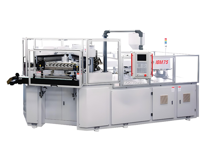
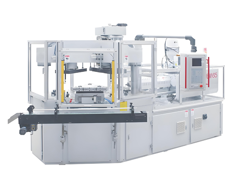
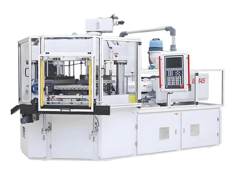
The discussion encompasses the full spectrum of mold types encountered in this industry, from single cavity prototypes to multi cavity production tools running on an injection blow molding machine like the IBM55 or IBM75. We examine core pin construction and alignment, cavity steel selection, gate placement strategies, conformal cooling channel design, surface finish requirements for release and clarity, expected tool life under continuous operation, and the maintenance intervals necessary to preserve dimensional accuracy over millions of cycles. Understanding these factors allows engineers to predict how a mold will perform before cutting steel, reducing costly trial and error during commissioning.
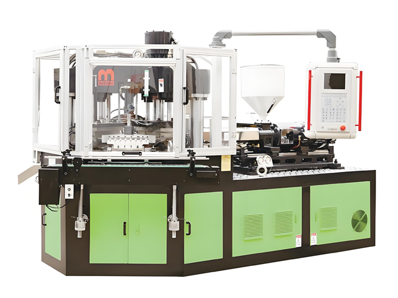
AiBiM manufactures injection blow molding machines designed to work in tandem with precisely engineered molds. Our equipment provides the clamping force, shot control, and rotary indexing needed to support complex tooling, but the final bottle quality rests on the mold itself. The following table summarizes key mold components, their primary function within the process, and their direct impact on finished container quality.
| Mold Component | Primary Function | Impact on Bottle Quality |
|---|---|---|
| Core Pin | Forms internal cavity shape | Wall thickness uniformity |
| Cavity Steel | Defines outer bottle profile | Surface finish and clarity |
| Gate System | Controls melt entry | Flow balance and stress |
| Cooling Channels | Removes heat from polymer | Cycle time and shrinkage |
By the end of this article, you will possess a practical framework for evaluating mold designs against your specific production requirements. You will understand how to specify tooling that maximizes output on your injection blow molding machine while minimizing defects such as flash, short shots, or uneven wall distribution. This knowledge empowers you to collaborate effectively with mold makers and troubleshoot existing tools without relying solely on trial adjustments during live production runs.
Injection Blow Molds and Blow Molds
The Two Stage Process Inside One Machine
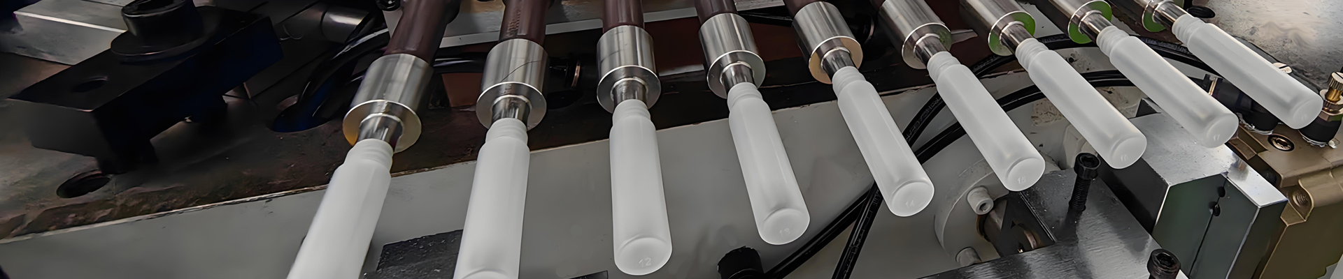
In single stage processing, two distinct mold sets operate in sequence on the same rotary platform of an injection blow molding machine. The first set is the injection mold, which forms a preform by injecting molten polymer around a core pin. This preform contains the finished neck finish and threaded closure interface, as these features are formed during the initial injection phase rather than during blowing. The second set is the blow mold, which encloses the heated preform and expands it into the final bottle shape using compressed air. These molds must align perfectly with each other through precise rotary indexing to ensure the core pin carrying the preform enters the blow cavity without collision or misalignment.
Injection Mold Construction and Preform Formation
The injection mold consists of a fixed half containing the nozzle entry and gate, and a moving half holding the core pins. Each core pin is mounted on a rotating carrier that moves from station to station. The cavity around each core defines the preform outer diameter, while the core itself forms the inner bore and neck threads. Steel selection for this mold must resist abrasion from glass filled or reinforced resins common in pharmaceutical applications. Typical tooling costs for a four cavity injection mold range from 15000 to 45000 US dollars depending on steel grade, complexity of thread form, and cooling channel density. This cost estimate varies by region and supplier but reflects current market rates for precision machined tooling.
Blow Mold Geometry and Air Expansion Dynamics
The blow mold features a cavity that matches the final bottle profile exactly. When the preform is transferred to this station, it is reheated if necessary or blown directly while still warm depending on resin type. Compressed air at pressures between 20 and 40 bar forces the polymer outward against the cold steel walls. The blow mold must withstand these internal pressures without flexing, as even slight deflection alters wall thickness distribution. Vent channels in the blow cavity allow trapped air to escape during expansion, preventing bubbles or incomplete fill at corners and shoulders.
Coordination Between Mold Sets for Quality Consistency
Successful production requires thermal and mechanical synchronization between the injection and blow molds. The core pin must maintain dimensional stability across both stages because it serves as the mandrel for blowing in many designs. Misalignment exceeding 0.1 millimeters can cause uneven wall thickness or flash at the neck finish junction. Regular inspection of mating surfaces ensures that the transition from preform to bottle remains seamless throughout the tool life.
Core Pin Design and Wall Distribution
Geometry Control of Preform Thickness
The core pin is the central mandrel around which molten polymer flows during injection. Its outer diameter directly determines the inner bore of the preform, while the distance between the pin surface and the cavity wall sets the initial wall thickness. For pharmaceutical bottles requiring strict barrier properties, this dimension must be held within tolerances of plus or minus 0.05 millimeters across every cavity in a multi cavity tool. Any deviation results in inconsistent material distribution after blowing. The core pin also carries the neck finish geometry, including thread forms and sealing surfaces, which are formed with high precision to ensure closure compatibility. Replacing worn pins typically costs between 200 and 800 US dollars per unit depending on complexity and steel grade, making initial design accuracy economically significant over long production runs.
Taper and Radius for Uniform Expansion
During the blow stage, the preform expands radially against the mold cavity. If the core pin has a uniform cylindrical shape, material tends to thin excessively at the center of the bottle body while remaining thick near the base and shoulder. To counteract this, engineers design core pins with specific taper angles and transition radii. A slight outward taper from base to neck encourages more even stretching along the vertical axis. The radius where the pin meets the neck finish is particularly critical; a sharp corner creates stress concentration and poor flow, while an overly large radius wastes material in the heel area of the bottle. Optimizing these curves ensures that wall thickness varies by less than ten percent from the thinnest to the thickest point in the final container.
Thermal Conductivity and Surface Finish
Core pins act as heat sinks during the cooling phase of injection. If a pin runs too hot, the preform sticks or deforms upon ejection; if it runs too cold, the polymer freezes prematurely, causing short shots or high viscosity issues. Internal cooling channels within the pin maintain stable temperatures, often using water flow rates of 0.5 to 1.5 liters per minute per channel. Surface finish on the pin affects release friction and preform clarity. A mirror polish reduces drag but may trap air bubbles if not vented properly. In high speed production on an injection blow molding machine like the IBM65, even minor surface defects on the pin translate directly into visible marks on every bottle produced. Regular polishing or coating replacement extends tool life and maintains dimensional integrity.
Cavity Layout and Clamp Matching
Balancing Cavity Count with Machine Capacity
Selecting the number of cavities in an injection blow molding machine mold is a direct trade off between output volume and tooling complexity. A single cavity tool might produce 1000 bottles per hour, while a four cavity layout on the same platform can quadruple that rate if cycle times remain stable. However, adding cavities increases the projected area exposed to injection pressure. For a typical pharmaceutical bottle with a preform mass of 5 grams, each additional cavity adds approximately 2 to 3 tons of clamping force requirement depending on resin viscosity and shot size. The mold layout must fit within the platen dimensions of the machine, such as those found in the IBM75, ensuring that all core pins and cavities remain within the tie bar spacing without overhanging the support plates.
Platen Size Constraints and Tool Weight
The physical footprint of the mold is limited by the available platen area. A four cavity tool for 20 milliliter vials might measure 400 by 600 millimeters, while a twelve cavity layout for larger containers could exceed 800 by 1000 millimeters. Larger molds require heavier steel plates to resist deflection under pressure, often weighing between 500 and 1500 kilograms. This weight impacts the handling requirements during mold changes and influences the thermal mass that must be heated and cooled during startup. Engineers must verify that the machine’s tie bar spacing accommodates not just the outer dimensions of the mold but also the internal cooling manifolds and ejector systems. Exceeding platen limits leads to uneven clamping, where the center of the mold remains open while the edges are sealed, causing flash at critical seal surfaces.
Clamping Force Requirements for Flash Prevention
Clamping force must exceed the total projected area multiplied by the injection pressure to prevent molten polymer from escaping between parting lines. For high viscosity resins used in medical containers, peak pressures can reach 1500 bar during packing. If the clamping force is insufficient, flash forms at the neck finish or base, requiring secondary trimming operations that add cost and risk contamination. A rule of thumb suggests providing at least 20 percent margin above calculated requirements to account for machine wear and resin variability. Upgrading from a smaller injection blow molding machine to a larger unit solely to support more cavities often costs between 50000 and 150000 US dollars, so optimizing cavity count within existing capacity is usually the preferred engineering approach. Proper alignment of the mold halves ensures that this force is distributed evenly across all cavities rather than concentrating on one side.
Gate Design and Weld Lines
Strategic Placement of Entry Points
The gate is the narrow channel through which molten polymer enters the preform cavity. In injection blow molding machine applications, this location dictates how material flows around the core pin and fills the neck finish threads. A direct gate at the base of the preform is common for small containers because it simplifies mold construction and allows easy trimming of the gate vestige. However, placing the gate directly under the neck can create stress concentrations that lead to cracking during capping or filling. Engineers often offset the gate slightly or use a ring gate to distribute flow evenly around the circumference. This strategy reduces orientation effects in the polymer chains, which otherwise cause anisotropic strength properties in the final bottle wall.
Flow Balance Across Multiple Cavities
In multi cavity tools, melt distribution must be identical for every core pin to ensure consistent preform weight and dimensions. If one cavity fills faster than another, it cools at a different rate, leading to variations in shrinkage and subsequent blow molding behavior. Manifold design achieves this balance by adjusting runner diameters so that the pressure drop across each path is equal. For a four cavity mold on an IBM55, the difference in preform weight between cavities should not exceed 0.1 grams to maintain quality standards. Unbalanced flow results in some bottles having thicker walls while others are thin and prone to failure under vacuum or internal pressure. Regular balancing tests using clear resin or simulation software help identify discrepancies before steel is cut.
Managing Weld Line Integrity
Weld lines form when two fronts of molten polymer meet inside the cavity, typically around the core pin or at the end of flow paths. These junctions are structurally weaker because the polymer chains do not entangle fully due to premature cooling. In pharmaceutical bottles, weld lines often appear near the shoulder or base where flow splits around obstacles. To minimize their impact, designers increase melt temperature and injection speed to improve fusion quality. Alternatively, gate placement can be adjusted so that weld lines occur in low stress areas rather than on functional surfaces like thread roots. A poorly formed weld line can reduce burst pressure strength by up to 30 percent compared to the bulk material. Repairing mold flow issues after production begins is costly, often requiring new insert fabrication costing between 500 and 2000 US dollars per cavity.
Cooling Channels and Cycle Time
Optimizing Channel Layout for Heat Removal
The primary bottleneck in injection blow molding is often thermal management rather than mechanical speed. Cooling channels must be positioned close to the cavity surface to extract heat efficiently, yet they cannot compromise structural integrity of the steel block. Standard drilled channels typically run 6 to 12 millimeters below the cavity face, maintaining a minimum wall thickness of 3 to 5 millimeters to prevent hot spots. In complex geometries like neck finishes or threaded closures, conformal cooling channels that follow the contour of the part are superior but require additive manufacturing techniques. These advanced methods can reduce cycle times by 15 to 20 percent compared to conventional straight drilled holes. The cost for such specialized tooling increases significantly, potentially adding 30 to 50 percent to the initial mold price, which ranges from 20000 to 60000 US dollars for standard configurations.
Temperature Uniformity and Dimensional Stability
Uneven cooling leads to differential shrinkage, causing bottles to warp or exhibit ovality issues. If one side of a preform cools faster than the other, internal stresses develop that manifest as distortion after ejection. To prevent this, temperature sensors embedded near critical features monitor real time conditions during production on an injection blow molding machine like the IBM75. Maintaining mold surface temperatures within plus or minus 2 degrees Celsius across all cavities ensures consistent polymer crystallization rates. For semi crystalline resins such as PET or PP, even slight temperature variations alter crystal structure and barrier properties. Uniform cooling also prevents sink marks near thick sections like the bottle base, preserving aesthetic quality and functional fit for secondary packaging systems.
Impact on Production Rates and Efficiency
Cycle time is directly proportional to the thermal mass of the part and the efficiency of heat transfer. Reducing cooling time by just two seconds can increase hourly output by 10 to 15 percent on high speed lines. For a four cavity tool running at 20 cycles per minute, this translates to an additional 480 bottles per hour. Over a year, this gain represents significant revenue potential, often offsetting the higher initial investment in optimized cooling designs. However, aggressive cooling can cause surface freezing before the core solidifies, leading to trapped voids or poor fusion at weld lines. Engineers must balance rapid heat extraction with sufficient dwell time to allow complete packing and holding pressure phases. Properly designed cooling systems also reduce energy consumption by minimizing the load on external chillers, lowering operational costs while maintaining strict dimensional tolerances required for pharmaceutical container specifications.
Steel Selection and Surface Finish
Tool Steel Grades for Durability and Corrosion Resistance
The choice of steel dictates how long a mold survives under continuous operation on an injection blow molding machine. For high volume pharmaceutical production, pre hardened stainless steels such as 420SS or 17-4PH are common because they resist corrosion from acidic resins and cleaning agents. These materials typically achieve hardness levels between 40 and 50 HRC after heat treatment. Softer carbon steels like P20 may be used for short run prototypes or low volume applications where tooling costs must remain under 10000 US dollars per cavity set. However, they wear rapidly when exposed to glass filled polymers or abrasive additives found in barrier resins. Hardened tool steels such as H13 offer superior resistance to thermal fatigue cracking but require careful machining and polishing due to their higher initial cost and processing difficulty. Selecting the right grade ensures that dimensional tolerances remain stable over millions of cycles without frequent rework.
Surface Texture Control for Optical Clarity
Surface finish directly impacts the visual quality of clear plastic containers used in medical packaging. A mirror polish with a roughness average below 0.1 micrometers is required for optical clarity, allowing light to pass through the bottle wall without scattering. Any scratches or pits on the cavity surface transfer directly to the polymer, creating visible defects that lead to rejection during inspection. Achieving this finish demands skilled hand polishing or advanced electrochemical techniques after initial machining. Textured finishes are sometimes applied intentionally to mask flow lines or provide grip surfaces on non transparent bottles. However, texture must be uniform across all cavities to prevent inconsistent appearance. Regular maintenance involves cleaning and re polishing inserts every 500000 to 1 million cycles to remove buildup and restore surface integrity.
Hardness Matching for Wear Resistance
Core pins experience significant mechanical stress during ejection and blow stages. If the pin is softer than the resin or its additives, it will abrade quickly, leading to flash and poor thread definition. Conversely, overly hard pins can become brittle and crack under thermal cycling. A hardness differential of at least 5 HRC between mating parts often reduces galling and seizure. Coatings such as titanium nitride or diamond like carbon can increase surface hardness by 1000 to 2000 HV, extending life significantly. Applying these coatings adds 200 to 500 US dollars per pin but can double the interval between replacements. Proper lubrication during assembly and operation also prevents metal on metal contact that accelerates wear.
Tool Life and Maintenance
Wear Mechanisms in High Cycle Production
Mold life is measured in millions of cycles rather than years of calendar time. A well maintained tool on an injection blow molding machine like the IBM65 can produce 1 to 3 million bottles before significant dimensional drift occurs. The primary wear mechanisms are abrasive erosion from glass filled resins, adhesive transfer from polymer buildup, and fatigue cracking at stress concentrators such as sharp corners or cooling channel intersections. Core pins suffer the most because they experience both thermal cycling and mechanical friction during ejection. Even a wear rate of 0.01 millimeters per million cycles can accumulate enough deviation to cause flash or neck finish non conformance. Monitoring critical dimensions with coordinate measuring machines every 500000 cycles helps predict failure before scrap rates exceed acceptable limits.
Cleaning Protocols for Residue Control
Polymer residue, often called mold deposit, accumulates on cavity surfaces and core pins over time. This buildup creates surface imperfections that transfer to the bottle, resulting in visible defects or barrier failures. Dry ice blasting is a preferred cleaning method because it removes contaminants without damaging polished steel surfaces. Ultrasonic baths are effective for small inserts but cannot reach deep cooling channels. Regular cleaning intervals depend on resin type; polypropylene requires less frequent attention than PVC or nylon due to lower residue formation. Cleaning costs typically range from 500 to 1500 US dollars per mold set, depending on complexity and labor rates in the region. Neglecting this step leads to increased cycle times as operators slow down to prevent sticking, reducing overall equipment effectiveness.
Refurbishment and Component Replacement Strategies
When wear exceeds repair limits, refurbishment involves welding and re machining damaged areas or replacing entire inserts. Replacing a single core pin costs between 200 and 800 US dollars plus labor, while rebuilding a full cavity block may cost 5000 to 10000 US dollars. Many manufacturers keep spare pins and cavities in inventory to minimize downtime during unexpected failures. This strategy is particularly important for pharmaceutical lines where regulatory validation makes mold changes complex and time consuming. Proper storage of spare parts prevents corrosion and damage, ensuring they are ready for immediate installation. Documenting maintenance history allows engineers to correlate wear patterns with specific operating conditions, enabling design improvements in future tool generations.
Cost and Price Analysis of IBM Tooling
Indicative Budget Ranges for Production Molds
Tooling costs vary significantly based on cavity count, steel grade, cooling complexity, and geographic manufacturing location. The following table provides rough budget estimates in US dollars for typical pharmaceutical or packaging container molds used with AiBiM equipment. These figures assume standard carbon or stainless steels without exotic coatings or additive manufactured conformal cooling channels. Actual quotes will differ by region and supplier capabilities.
| Tooling Item | Price Range USD | Main Cost Driver |
|---|---|---|
| Single Cavity Mold | 15000 to 30000 | Steel volume and machining time |
| Four Cavity Set | 40000 to 80000 | Flow balancing and alignment precision |
| Replacement Core Pins | 200 to 800 per unit | Precision grinding and heat treatment |
| Surface Refurbishment | 1000 to 3000 | Labor hours for polishing and cleaning |
Calculating Cost Per Bottle and Payback Period
To determine economic viability, engineers must amortize the initial tooling investment over the expected production volume. For a four cavity mold costing 60000 US dollars running on an IBM75 at 20 cycles per minute, annual output might reach 10 million bottles. This results in a tooling cost of only 0.006 US dollars per bottle. If the selling price is 0.10 US dollars, the margin remains healthy even after accounting for resin and energy costs. However, if production volumes drop to 1 million bottles annually due to market fluctuations, the amortized cost rises to 0.06 US dollars per unit, potentially eroding profitability.
Caveats on Regional Pricing and Hidden Costs
These price ranges are indicative budgets only and exclude taxes, shipping, import duties, or installation fees which can add 10 to 20 percent to the total project cost. Labor rates for mold making vary widely; a tool produced in North America may cost twice as much as one made in Asia, though lead times and communication ease often justify the premium for complex pharmaceutical designs. Additionally, hidden costs include spare parts inventory, regular maintenance contracts, and potential downtime during mold changes. A poorly designed mold that requires frequent adjustments or early refurbishment will have a higher total cost of ownership than a more expensive but robust initial tool. Therefore, prioritizing quality in steel selection and cooling design often yields better long term returns than minimizing upfront capital expenditure.
Mold Setup and Changeover
Installation and Mechanical Alignment Procedures
Installing a new mold on an injection blow molding machine requires precise mechanical alignment to ensure the rotary indexing mechanism synchronizes correctly with the stationary platen. Technicians first clean all mounting surfaces to remove debris that could cause uneven clamping or misalignment. The mold is lifted into position using overhead cranes or hoists, then secured with T slots and clamp bars. Critical to this process is verifying that the core pin carrier aligns perfectly with the blow cavity station. A lateral offset of even 0.2 millimeters can cause preform collision during transfer, leading to immediate scrap. Dial indicators are used to check parallelism between the injection and blow mold halves, ensuring they remain within 0.05 millimeters across the entire platen area.
Thermal Stabilization and Parameter Optimization
Once mechanically secured, the mold must reach thermal equilibrium before production begins. Water temperature controllers circulate fluid through internal channels until sensor readings stabilize at the target set point, typically between 100 and 140 degrees Celsius for polypropylene applications. This warm up phase can take 30 to 60 minutes depending on tool mass. During this time, operators input initial process parameters such as injection speed, holding pressure, and blow pressure based on resin data sheets. On machines like the IBM55, these settings are often stored in preset recipes to reduce trial and error. Gradual ramping of injection volume allows engineers to observe fill patterns without risking short shots or excessive stress on the machine hydraulics.
First Article Inspection and Quality Verification
Before full production starts, first article inspection validates that the mold produces containers within specification. Samples are measured for critical dimensions including neck finish diameter, wall thickness distribution, and overall height using coordinate measuring machines or optical comparators. Any deviation triggers adjustments to cooling flow rates or injection timing rather than immediate steel modification. For pharmaceutical clients, this step often includes leak testing and visual inspection under magnification to detect micro defects. Successful first article approval typically requires producing 10 to 20 consecutive good parts without adjustment. This rigorous verification prevents costly rejections later in the run and ensures regulatory compliance for medical packaging standards.
Routine Mold Care
Cleaning Protocols for Surface Integrity
Maintaining surface cleanliness is essential for preserving bottle quality on an injection blow molding machine like the IBM75. Polymer residue accumulates on core pins and cavity walls, creating micro defects that transfer to subsequent containers. Dry ice blasting offers a non abrasive cleaning method that removes deposits without altering steel dimensions or damaging polished finishes. This technique requires specialized equipment costing between 5000 and 15000 US dollars, but it significantly reduces downtime compared to manual scrubbing with copper brushes which can scratch critical surfaces. For less aggressive resins, ultrasonic baths effectively clean small inserts and core pins by dislodging contaminants through cavitation. Regular cleaning intervals should be established based on resin type and production volume, typically every 200000 to 500000 cycles for high clarity applications.
Lubrication of Moving Components
Mold components such as ejector pins, guide columns, and rotary bearing surfaces require periodic lubrication to prevent seizure and wear. High temperature silicone based greases are preferred because they withstand mold temperatures up to 200 degrees Celsius without degrading or migrating into the cavity. Applying too much lubricant risks contamination of the preform, leading to adhesion issues during blowing. Technicians must use precision applicators to deposit small amounts on moving interfaces only. Guide pins and bushings should be inspected for galling every 10000 cycles; early detection prevents catastrophic failure that could damage both the mold and the machine platen. Proper lubrication extends component life by reducing friction heat and metal transfer, ensuring smooth ejection and indexing actions throughout long production runs.
Storage Conditions for Idle Tools
When molds are not in use, proper storage prevents corrosion and physical damage. Steel surfaces must be coated with a protective anti rust oil or vapor phase inhibitor paper to block moisture exposure. Molds should be stored in climate controlled environments with humidity below 40 percent to prevent oxidation on polished cavity faces. Core pins and inserts are often removed and packed separately in foam lined containers to avoid accidental impact during handling. Storing heavy mold blocks vertically or horizontally depends on structural design, but all mounting plates must remain flat to ensure future alignment accuracy. Documenting storage location and condition helps technicians verify integrity before reinstalling tools onto the production line after extended periods of inactivity.
How AiBiM Supports Tooling
Machine Design for Mold Compatibility
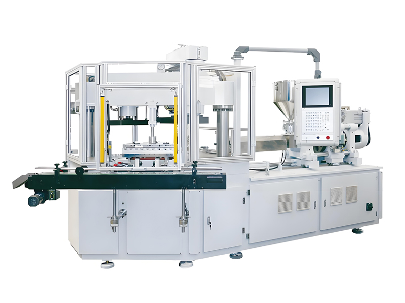
AiBiM manufactures injection blow molding machines including the IBM55, IBM65, and IBM75 models, each engineered with precise rotary indexing systems that accommodate complex multi cavity tooling. The structural rigidity of these platforms ensures minimal deflection under high clamping forces, allowing molds to maintain alignment over millions of cycles. This mechanical stability is critical for pharmaceutical containers where neck finish tolerances must remain within microns. By providing consistent platen parallelism and reliable servo driven rotation, the machines reduce the burden on mold designers to compensate for machine induced variations. Engineers can focus on optimizing core pin geometry and cooling channels rather than adapting tooling to accommodate equipment limitations.
Process Integration for Consistent Output
Successful production requires seamless integration between the injection blow molding machine controls and the mold thermal management system. AiBiM equipment offers advanced temperature control interfaces that monitor individual zones, ensuring uniform heat distribution across all cavities. This capability allows operators to fine tune cooling water flow rates in real time to correct minor dimensional deviations without stopping production. The human machine interface provides access to critical parameters such as injection pressure profiles and blow timing sequences, facilitating rapid adjustments during first article trials. These features support efficient mold setup by reducing the number of trial runs needed to achieve stable process windows.
Technical Collaboration for Tooling Success
AiBiM technical teams work directly with mold makers to verify that tool designs match machine specifications before fabrication begins. This collaborative approach prevents costly mismatches in tie bar spacing, ejector stroke lengths, or cooling manifold connections. During commissioning, AiBiM engineers assist in aligning rotary stations and validating cycle times to ensure the mold performs as intended. Post installation support includes troubleshooting process variations that may stem from tool wear or thermal drift. By understanding both machine dynamics and mold physics, AiBiM helps customers achieve high quality output while maximizing tool life on their injection blow molding machine platforms.
Conclusion
Mold design is the primary determinant of bottle quality in injection blow molding operations. The geometry of core pins dictates wall thickness distribution, while cavity layout and gate placement control flow balance and weld line integrity. Effective cooling channel architecture directly influences cycle time efficiency and dimensional stability, reducing scrap rates and energy consumption. Selecting appropriate steel grades and surface finishes extends tool life, protecting capital investment against abrasive wear and thermal fatigue. These engineering decisions collectively define the economic viability of production runs on platforms like the IBM55 or IBM75.
Understanding these interdependent factors allows manufacturers to optimize total cost per bottle rather than focusing solely on initial tooling price. A well designed mold minimizes maintenance intervals, reduces downtime during changeovers, and ensures consistent output that meets strict pharmaceutical and packaging standards. Poor design choices lead to hidden costs through increased scrap, frequent refurbishment, and reduced machine uptime. Therefore, rigorous evaluation of core pin taper, cooling uniformity, and clamping force requirements is essential before committing to steel fabrication.
AiBiM provides injection blow molding machines engineered to support high precision tooling for small container applications.