Injection Blow Molding Mold Design: How Core Pins, Cavities, Gates and Cooling Channels Control Bottle Quality, Cycle Time and Tooling Cost
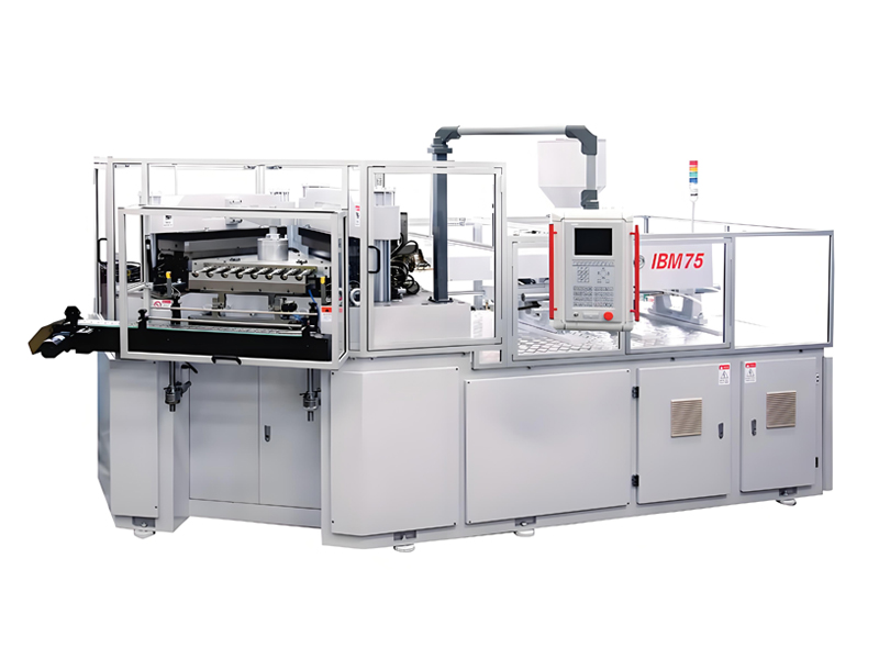
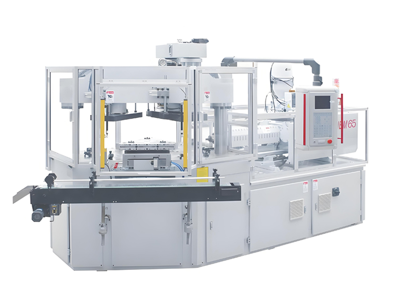
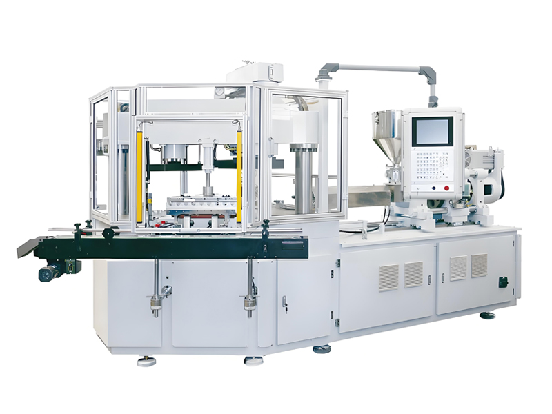
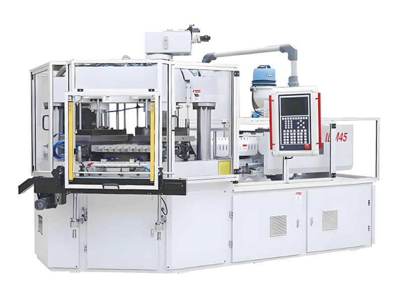
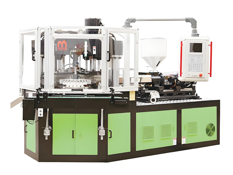
In injection blow molding, the mold is where bottle quality, cycle time and cost are truly decided, more than the machine alone. The process follows a three station one step sequence: injection of a parison onto a core pin, transfer to the blow station, and stripping of the finished bottle. This guide covers core pin and cavity design, gates, cooling, venting, steel selection, surface finish, multi cavity tooling, defect diagnosis, maintenance and a full cost analysis. AiBiM Plastic Machinery is an Injection Blow Molding Machine Manufacturer with real model names IBM55, IBM65 and IBM75. Tooling costs typically range from fifteen thousand to eighty thousand US dollars depending on complexity, though these are indicative budget ranges requiring specific quotation. The reader will gain practical engineering knowledge to optimize production efficiency, reduce scrap rates and make informed tooling investments for high volume packaging applications.
Why Tooling Decides Quality, Output and Cost
The mold dictates every physical characteristic of the final container. A precisely engineered tool ensures uniform wall thickness, accurate neck finish dimensions, and defect free surfaces while maintaining short cycle times. Conversely, a poorly designed or worn mold introduces flash, uneven walls, extended cooling periods, and elevated scrap rates. These flaws do not remain isolated incidents; they propagate rapidly through production. A minor dimensional error on a core pin can cause millions of bottles to fail pressure tests or leak over their lifespan. Since molds endure millions of cycles, small initial design choices compound into massive operational consequences.
Consider the financial impact. On a medium output line producing two million units annually, a badly designed or worn mold might generate a five percent scrap rate. This equates to one hundred thousand rejected bottles per year. At an average material and processing cost of fifteen cents per unit, this represents fifteen thousand dollars in direct annual waste. This figure is indicative and varies based on resin prices, machine speed, and labor rates. However, it highlights why tooling investment cannot be minimized without risk. The mold must interact seamlessly with the Injection Blow Molding Machine to maintain thermal stability and mechanical precision. A reliable Injection Blow Molding Machine Manufacturer understands that tooling quality directly influences machine efficiency. Investing in high grade steel and precise cooling channel layout reduces long term operating costs far more than saving on initial tool fabrication.
How the Three Station Process Shapes Mold Design
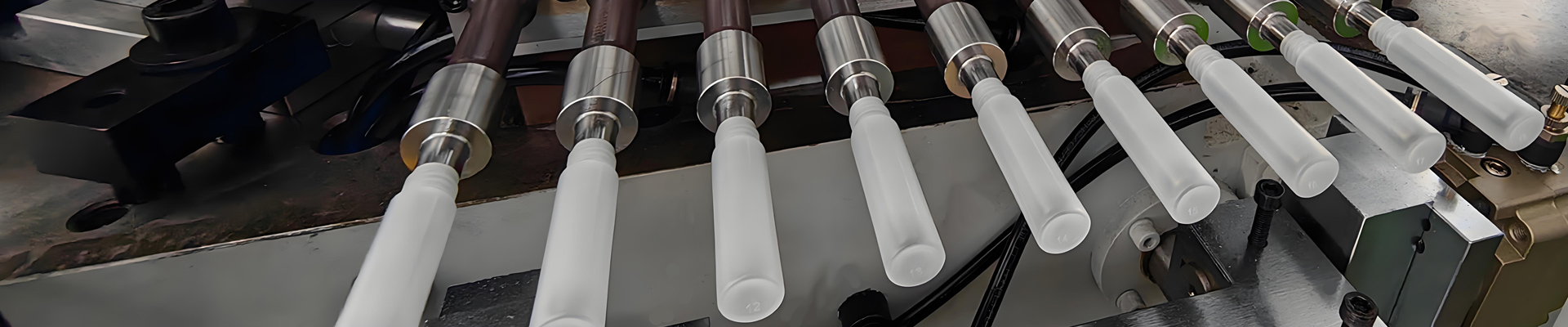
The three station one step sequence fundamentally dictates mold architecture in Injection Blow Molding Machine operations. At the injection station, the core pin defines the internal geometry while the cavity shapes the external surface and neck finish. This requires precise mating to ensure uniform wall thickness. The parison then moves to the blow station where compressed air expands it against a cooled blow cavity. Here, thermal management is critical because rapid heat extraction solidifies the bottle shape efficiently. Finally, the stripper station removes the finished container without distortion. A single core pin travels through these distinct thermal environments, transitioning from hot injection conditions to cool blowing zones. This thermal cycling demands exceptional dimensional stability in tool steel to prevent warping or mismatch that causes flash or weak spots. Alignment across all three stations must remain within tight tolerances, typically under two hundredths of a millimeter, to maintain part consistency. Any misalignment leads to scrap and increased cycle time. The design accommodates capacities ranging from tiny 3 milliliter vials to large 1000 milliliter jars, requiring scalable mold bases that balance rigidity with cooling efficiency. For an Injection Blow Molding Machine Manufacturer, tooling costs for a four cavity mold typically range from twenty five thousand to sixty thousand US dollars depending on complexity and steel grade. This investment is justified by high throughput and reduced secondary operations. Proper integration of core pins, cavities, gates, and cooling channels ensures that the final product meets strict dimensional specifications while maximizing production speed and minimizing long term maintenance expenses for the entire system.
Core Pin Design and Its Role in Wall Thickness
The core pin stands as the absolute heart of any injection blow mold because it simultaneously forms the precise interior geometry of the bottle and transports the molten parison between processing stations within an Injection Blow Molding Machine. Its physical dimensions, including diameter, length, taper rate, and tip geometry, directly dictate the final wall thickness profile at both the critical base and the sidewalls. A slight deviation in taper angle can cause uneven material distribution that leads to structural weakness or excessive resin usage. During operation, the pin absorbs significant thermal energy from the injected polymer melt before being cooled between cycles to maintain dimensional stability. Achieving strict temperature balance along the entire length of the pin is essential because thermal gradients alter local viscosity and flow behavior, which in turn shifts parison thickness unpredictably. If one section runs hotter than another, the plastic will stretch unevenly during blowing, creating thin spots that may fail under pressure or drop testing. For tall containers, rigidity becomes a primary design constraint since slender pins are prone to deflection under mechanical load and thermal expansion. Even minor bending can cause wall thickness variations that compromise packaging integrity. A skilled Injection Blow Molding Machine Manufacturer will often incorporate internal cooling channels within the pin body to manage heat extraction efficiently while preserving structural stiffness. Replacing worn core pins is a routine maintenance task, but costs vary widely based on steel grade, surface treatment, and precision grinding requirements. An indicative budget for a replacement set of four hardened steel core pins typically ranges from 800 to 2500 US dollars depending on complexity and regional labor rates. This estimate assumes standard tooling without exotic coatings or ultra tight tolerances. Always verify specific supplier quotes because specialized alloys and complex internal cooling circuits can significantly increase the final price tag beyond these baseline figures.
Blow Cavity Design and Parison Expansion
The blow cavity defines the final bottle geometry and surface finish, making its design critical for dimensional accuracy. Parting lines must align precisely with functional features like handle grips or shoulder radii to ensure they remain visually hidden on the finished container. Any misalignment creates visible flash that requires costly secondary trimming. Proper alignment reduces scrap rates significantly, keeping annual tooling maintenance budgets between fifteen thousand and forty thousand US dollars depending on cavity count and steel grade.
During inflation, the parison expands rapidly against the cold cavity wall. Air flow dynamics within the cavity are vital for filling sharp corners and complex handle geometries without trapping air. Venting channels, often microscopic grooves etched into the steel, allow trapped air to escape, preventing incomplete fills or thin spots. Without adequate venting, cycle times increase as operators slow down inflation pressure to compensate for poor fill, reducing output by up to twenty percent.
Surface finish directly transfers to the bottle. Polished cavities produce glossy containers suitable for premium cosmetics, while textured finishes provide grip and hide minor defects in industrial chemicals. Texture depth typically ranges from five to fifty microns, influencing both aesthetics and mold release characteristics. Cavity material selection impacts thermal management. Hardened tool steel with high thermal conductivity ensures rapid heat removal, shortening cooling time by several seconds per cycle. This efficiency is essential for high speed production runs on machines like the IBM65 or IBM75. A competent Injection Blow Molding Machine Manufacturer will specify appropriate steel grades and cooling channel layouts to balance initial tooling investment against long term operational savings, ensuring consistent quality across millions of cycles.
Neck and Thread Forming
The neck represents the most dimensionally critical feature of any container because it must seal reliably against a closure. In injection blow molding, this geometry is formed entirely within the injection cavity surrounding the core pin. The mold inserts precisely shape the thread profile, pitch, and sealing land while also defining tamper evident rings or other security features. Any deviation in these areas directly compromises leak performance and restricts capping line speed. High speed rotary cappers demand tight concentricity to prevent cross threading or stripping during application.
Typical neck diameter tolerances range from plus or minus zero point zero five millimeters for standard pharmaceutical bottles, though this varies by material and cap type. This indicative budget range assumes high precision tooling costs between fifteen thousand and forty thousand US dollars per cavity set, depending on complexity. A skilled Injection Blow Molding Machine Manufacturer ensures these tolerances are maintained through rigorous steel selection and surface finishing.
Wear in the neck ring inserts is a primary cause of leaking caps over time. As the hard chrome plated or hardened tool steel wears, the thread crests flatten and the sealing land loses its sharp definition. This allows gas or liquid to escape past the cap liner. Regular inspection using optical comparators or coordinate measuring machines detects this degradation early. Replacing worn neck rings restores dimensional accuracy without scrapping the entire mold base, offering a cost effective maintenance strategy for long production runs on any Injection Blow Molding Machine.
Gate Systems and Where Melt Enters the Mold
The gate serves as the critical entry point where molten plastic transitions from the runner system into the mold cavity, exerting profound influence on final bottle quality and production efficiency. In injection blow molding applications, center pin gates located at the bottle base are standard because they facilitate clean separation and minimize visible defects on the container surface. Side or edge gates appear less frequently but may be necessary for specific geometries where bottom access is restricted. The physical dimensions of the gate, specifically its cross sectional area and land length, directly dictate melt shear rates and pressure drops during filling. A narrow gate increases shear heating which can degrade sensitive resins like PET, while an overly wide gate risks excessive flash and longer cooling times. Gate vestige, the small remnant left after separation, must be minimized to ensure aesthetic compliance and structural integrity. This is achieved through precise machining of the gate land and optimized ejection timing. In multi cavity tools, balanced filling relies on uniform gate sizing across all cavities. If one gate is restricted due to wear or design error, that cavity will fill slower than others, causing short shots or requiring increased injection pressure. This imbalance extends cycle time significantly. For a typical three station machine setup, correcting gate issues often requires tooling modifications costing between five hundred and two thousand dollars depending on complexity. An experienced Injection Blow Molding Machine Manufacturer designs these systems to ensure consistent flow dynamics. Proper gate engineering reduces scrap rates and supports stable high speed production cycles essential for cost effective packaging manufacturing.
Cooling Channel Design and Heat Removal
Cooling frequently accounts for forty to sixty percent of the total cycle time in injection blow molding operations, making heat removal strategy the primary lever for maximizing output rates from any Injection Blow Molding Machine. Effective thermal management requires precise channel placement within both the core pin and the final blow cavity. While traditional straight drilled channels are simple, conformal cooling channels that contour to the complex geometry of the bottle ensure uniform heat extraction across thin walls and thick bases. This geometric fidelity prevents localized hot spots that cause differential shrinkage, leading to warped bottles or inconsistent wall thickness distribution.
Design parameters such as channel diameter, distance from the mold surface, coolant flow rate, and inlet temperature must be optimized for each specific resin grade. Typical drilled channels range from six to ten millimeters in diameter, positioned eight to twelve millimeters from the cavity surface, though these figures vary significantly based on steel hardness and cooling requirements. Uneven cooling results in extended cycle times as the machine waits for the hottest zone to solidify, directly reducing production efficiency.
Conformal cooling technology, often achieved through additive manufacturing or specialized drilling, offers superior thermal uniformity but carries a higher initial tooling investment. The cost premium for conformal cooling inserts can range from fifteen thousand to thirty five thousand US dollars per mold set compared to conventional methods, depending on complexity and supplier capabilities. This figure is indicative and subject to change based on current steel prices and manufacturing lead times. Selecting the right Injection Blow Molding Machine Manufacturer with expertise in advanced thermal design ensures that this higher upfront cost translates into lower per unit production costs through faster cycles and reduced scrap rates.
Cycle Time, Cooling Time and Output
Cycle time in injection blow molding consists of four distinct phases including injection, blowing, cooling and ejection. Cooling invariably dominates this sequence because plastic must solidify sufficiently to maintain shape during demolding and subsequent handling. The required duration depends heavily on wall thickness, polymer thermal properties and coolant temperature. Heat transfer follows a square relationship with thickness meaning doubling the wall thickness quadruples the necessary cooling time. This physical constraint makes precise core pin geometry critical for uniform heat extraction. By optimizing cooling channel layouts within cavities and using efficient mold steels, manufacturers can shorten cycles significantly without requiring larger machinery. A well designed tool allows an Injection Blow Molding Machine to achieve higher hourly output from the same footprint. For small bottles around 500 milliliters typical cycle times range from eight to twelve seconds while medium containers of one liter often require twelve to eighteen seconds depending on resin type and complexity. These figures serve as indicative benchmarks only since actual performance varies with specific process conditions. Consider a production line running at ten cycles per minute. Reducing the cycle by just one second increases output by roughly six bottles per hour. On a high volume line producing two million units annually this improvement translates to approximately twelve thousand additional sellable units. At a conservative margin of five cents per unit that single second saves or earns about six hundred dollars yearly. Over multiple lines and years these gains justify the initial investment in advanced tooling from a reputable Injection Blow Molding Machine Manufacturer.
Venting and Air Removal
Trapped air is a primary enemy in injection blow molding because it prevents the parison from fully contacting the mold cavity surface. This phenomenon causes short fills, visible burn marks on the plastic, and structurally weak corners that fail pressure tests. Effective venting requires precise placement at the end of fill zones, along parting lines, and within deep recesses where air naturally accumulates during the blowing phase. The depth of these vents is critical to success. If a vent is too deep, molten polymer escapes easily, creating flash that requires manual trimming and increases labor costs significantly. Conversely, if a vent is too shallow, it fails to evacuate air quickly enough, leading to incomplete filling or surface defects. A typical maintenance routine involves cleaning vents every few thousand cycles to prevent blockage from carbonized residue. Blocked vents often manifest as recurring defects in only one cavity of a multi cavity mold, signaling localized issues rather than global machine faults. For a standard four cavity mold, professional vent refurbishment services typically cost between 150 and 400 US dollars per tooling set, though this varies by region and complexity. Proper design ensures consistent part quality and reduces scrap rates on any Injection Blow Molding Machine. An experienced Injection Blow Molding Machine Manufacturer will specify vent geometry early to avoid costly rework later in production.
Shrinkage and Dimensional Control
All thermoplastics shrink upon cooling, requiring mold cavities to be machined oversize for compensation. Typical linear shrinkage values vary significantly by material grade and processing conditions. Polyethylene exhibits 1.5 to 3.0 percent, while polypropylene ranges from 1.2 to 2.5 percent. Polystyrene is lower at 0.4 to 0.7 percent, and acrylonitrile butadiene styrene sits between 0.4 and 0.7 percent. Styrene acrylonitrile follows similar trends, whereas polycarbonate shows 0.5 to 0.8 percent and glycol modified polyethylene terephthalate copolyesters range from 0.2 to 0.6 percent. These figures are nominal; actual shrinkage depends heavily on wall thickness, cooling rate, and molecular orientation. Thicker walls cool slower, increasing crystallinity in semi crystalline resins like polyethylene, which raises shrinkage. Rapid cooling freezes molecules in place, reducing overall contraction but potentially locking in stress that causes warpage later. Orientation during the blow stage also affects dimensions differently along axial versus circumferential axes. Consequently, neck finishes often require different compensation factors than bottle bodies because they experience distinct thermal histories and mechanical stresses during preform injection and blowing. When a bottle falls out of specification on an Injection Blow Molding Machine, distinguishing between tooling wear and process drift is critical. First, verify that the core pin and cavity dimensions match original drawings using precise metrology. If tooling is within tolerance, adjust hold pressure, melt temperature, or cooling time to tune shrinkage. A consistent deviation across multiple cavities usually points to a process issue, whereas variation between cavities suggests tooling misalignment or wear. Corrective actions should begin with minor process adjustments before committing to costly mold repairs. Re cutting steel for dimensional correction can cost several thousand dollars per cavity depending on complexity and location. Therefore, rigorous initial dimensional validation during first article inspection prevents expensive re work later in the production cycle.
Surface Finish and Appearance
Cavity surface finish directly transfers to the bottle exterior, making it critical for cosmetic and pharmaceutical packaging where visual appeal dictates market success. A polished mirror finish, typically achieved through hand polishing or diamond turning on the cavity steel, produces high gloss bottles that reflect light sharply. This aesthetic is often required for premium personal care containers. Conversely, matte or frosted textures are created by bead blasting, etching, or laser texturing the mold surface. These finishes hide minor flow imperfections and provide a tactile quality valued in luxury branding. However, texture depth must be controlled carefully; excessive roughness increases friction during demolding, potentially causing drag marks on the polymer. Smooth surfaces reduce demolding forces, allowing faster cycle times on an Injection Blow Molding Machine by minimizing ejection resistance.
Surface condition also influences cleaning efficiency and maintenance intervals. Textured cavities trap residue more easily than polished ones, requiring more frequent tool cleaning to prevent contamination defects. Common appearance flaws like flow marks, weld lines, orange peel, and drag marks often stem from poor cavity preparation or inadequate gate design. Flow marks may indicate insufficient injection pressure or slow fill rates, while weld lines suggest improper venting or multi point gating issues. Orange peel typically results from low melt temperature or high injection speed relative to the cooling rate. Drag marks usually signal excessive demolding force due to tight tolerances or damaged surface coatings. Addressing these defects often requires tool modifications such as re polishing cavities, adjusting gate locations, or applying specialized release coatings. While initial tooling costs for high quality finishes can range from fifteen thousand to forty thousand US dollars depending on complexity and steel grade, the reduction in scrap rates and improved cycle efficiency justify this investment over time.
Steel Selection and Tool Life
Mold steel selection fundamentally dictates wear life, polishability, and corrosion resistance in injection blow molding applications. The core pin and cavity surfaces endure high thermal cycling and abrasive resin flow, requiring materials that balance toughness with surface hardness. Common tool steel families include pre hardened grades for shorter runs and through hardened steels for high volume production. For corrosive resins like certain nylons or additives, stainless steel options are mandatory to prevent pitting and degradation of the bottle surface finish. Heat treatment adjusts hardness, typically between 48 and 52 Rockwell C for standard steels, while higher ranges demand more rigorous processing. Surface coatings such as nitriding or chrome plating significantly enhance durability. Nitriding adds a hard, wear resistant case that can extend tool life by thirty to fifty percent, often costing an additional fifteen hundred to three thousand dollars per mold set. Chrome plating offers superior corrosion protection and release properties, adding two thousand to four thousand dollars depending on complexity. Material choice must align with projected production volume and resin chemistry. Selecting a cheaper steel for high cycle applications is frequently a false economy, as premature wear leads to costly repairs or total tool replacement. A basic aluminum mold might cost five thousand to eight thousand dollars, but it will not survive millions of cycles. Standard P20 steel molds typically range from fifteen thousand to thirty thousand dollars, offering a balanced lifespan for moderate volumes. Premium stainless steels can reach forty thousand to sixty thousand dollars, justified only when corrosion or extreme abrasion is present. An Injection Blow Molding Machine Manufacturer must weigh these initial investments against long term operational savings. Ultimately, the right steel minimizes downtime and ensures consistent bottle quality throughout the tool’s service life.
Multi Cavity Tooling and Balance
High volume production demands multi cavity tooling to maximize throughput from a single Injection Blow Molding Machine cycle. Moving from one to four or eight cavities fundamentally alters mold architecture and machine requirements. The primary engineering challenge is maintaining process balance so that every core pin receives identical melt pressure and temperature. Unbalanced runners cause some cavities to fill faster than others, leading to inconsistent cooling rates. This imbalance manifests as weight variations exceeding two percent and dimensional deviations beyond one hundredth of a millimeter between bottles from the same mold. Manufacturers measure this variation using precision scales and coordinate measuring machines to ensure statistical process control remains within tight tolerances.
Cavity count directly dictates clamping force requirements because larger projected areas demand higher tonnage to prevent flash. An AiBiM machine model such as the IBM55 suits two cavity molds, while the IBM65 handles four cavities, and the IBM75 supports eight or more. Selecting the correct Injection Blow Molding Machine Manufacturer ensures that hydraulic systems match these force demands without wasting energy. Tooling costs scale non linearly with complexity. A single cavity mold might cost fifteen thousand dollars, whereas a balanced eight cavity tool could range from sixty to eighty thousand dollars. These figures are indicative budget estimates and vary significantly based on steel grade, surface finish requirements, and regional labor rates. Proper balancing minimizes scrap and cycle time variance, making the higher initial investment in multi cavity tools economically viable for long production runs.
Tool Manufacturing, CNC and Quality Control
The journey from a digital concept to a functional injection blow molding mold begins with precise shrink analysis and three dimensional modeling. Engineers calculate material behavior for resins like PET or HDPE, ensuring core pins and cavities account for thermal contraction. Once the geometry is locked, computer numerical control machining carves the steel blocks. High speed mills remove bulk material quickly, while electrical discharge machines refine intricate gate details and cooling channel intersections. After roughing, molds undergo vacuum heat treatment to achieve surface hardness, typically between fifty two and sixty HRC, which extends tool life significantly. Skilled technicians then hand polish cavity surfaces to a mirror finish, reducing friction and improving bottle clarity.
In house manufacturing capability is critical for an Injection Blow Molding Machine Manufacturer. AiBiM Plastic Machinery operates its own advanced CNC center, producing both machine components and mold tools under one roof. This vertical integration drastically reduces lead times and enhances quality control. By managing every step from order confirmation through design, machining, testing, and delivery internally, the factory eliminates communication gaps common with outsourced vendors. A typical custom mold set costs between fifteen thousand and forty five thousand US dollars, depending on cavity count and complexity, though prices vary by region and material grade.
Before final acceptance, first article inspection is mandatory. Sampled bottles from trial runs are measured using coordinate measuring machines to verify wall thickness, neck finish dimensions, and overall volume. These physical measurements confirm that the mold performs as predicted in simulation. Only when every dimension falls within tight tolerances, often less than zero point one millimeter, is the tool approved for mass production on an Injection Blow Molding Machine.
Cost and Price Analysis of Injection Blow Molding Tooling
A single cavity prototype mold typically costs between eight thousand and fifteen thousand US dollars. A production single cavity mold ranges from fifteen thousand to thirty five thousand dollars. Multi cavity production molds, often used on an Injection Blow Molding Machine like the IBM55 or IBM75, cost fifty thousand to one hundred twenty thousand dollars depending on cavity count. A core pin set replacement runs between two thousand and six thousand dollars per set. Mold modification or partial replacement usually falls between three thousand and eight thousand dollars. These figures are rough budgets rather than quotes. Actual prices depend heavily on bottle size, cavity count, steel grade and supplier location.
Tooling investment breaks down into specific categories. Steel procurement accounts for fifteen to twenty percent of total cost. Precision machining consumes thirty to forty percent due to tight tolerances required for core pins and cavities. Heat treatment adds ten to fifteen percent to harden surfaces against wear. Polishing requires another ten to twenty percent, especially for high clarity bottles where surface finish dictates optical quality. Sampling and tryout costs add five to ten percent for initial validation runs.
Amortization depends on tool life and production volume. A hardened steel mold may last one million cycles. At a cycle time of eight seconds, this yields roughly four hundred thousand bottles per year per cavity. If scrap rates drop from three percent to zero point five percent with better cooling channel design, annual savings can exceed ten thousand dollars per cavity. Shorter cycles reduce material and labor costs significantly. For example, reducing cycle time by one second on a multi cavity mold saves substantial energy and machine hours annually. Investing in high quality steel and precise machining extends tool life, lowering cost per bottle over millions of cycles. Always verify quotes with an Injection Blow Molding Machine Manufacturer to align tooling specs with machine capabilities.
Troubleshooting Tool Related Bottle Defects
Uneven wall thickness in injection blow molding bottles typically originates from core pin misalignment or off center gate placement within the mold cavity. When the core pin shifts laterally by even a tenth of a millimeter, the parison forms asymmetrically, causing one side to stretch thinner during blowing. Corrective action requires precise regrinding of core pin guide bushings and verifying concentricity using coordinate measuring machines before reassembly. Flash formation along the parting line usually indicates worn sealing surfaces or excessive vent depth exceeding twenty micrometers. Worn steel at the cavity interface allows molten polymer to escape, creating sharp edges that compromise seal integrity. Repair involves laser welding the damaged parting line and recutting it to a flatness tolerance of two microns, while reducing vent depths to prevent gas trapping without allowing material leakage. Weld lines appear when gate positions force melt fronts to meet at low temperatures, often due to inadequate nozzle heating or restricted flow paths. Repositioning gates closer to the centerline or increasing barrel temperature by ten degrees Celsius can eliminate these weak points. Extended cycle times frequently result from scaling inside cooling channels, which acts as thermal insulation and reduces heat transfer efficiency significantly. Regular descaling with citric acid solutions restores performance, but severe cases require channel flushing or replacement, costing between five hundred and two thousand dollars depending on mold size. Dimensional drift over production runs stems from steel wear at critical dimensions or incorrect shrinkage factor calculations for specific resins like PET or HDPE. Rebuilding worn cavity inserts via hardfacing and remachining ensures tight tolerances within zero point zero five millimeters, preventing costly scrap rates during high volume production on any reliable Injection Blow Molding Machine Manufacturer platform.
Mold Maintenance, Cleaning and Life Extension
A rigorous preventive maintenance schedule is essential for preserving the integrity of injection blow molds used in high volume production. Technicians must clean vents and parting lines weekly to prevent gas trapping that causes short shots or surface defects. Core pins require inspection every fifty thousand cycles for bending or wear, as even minor deviations compromise wall thickness uniformity. Neck rings should be checked for flash accumulation, which can damage threads during ejection. Moving parts like ejector plates need regular lubrication with high temperature grease to reduce friction and heat buildup. Recording shot counts is critical for predicting fatigue failure before it occurs. Between production campaigns, molds must be stored in climate controlled areas with protective oil coatings to prevent corrosion on polished steel surfaces. Humidity control is vital, as rust forms quickly on carbon steel components left exposed. Scheduled refurbishment typically costs between fifteen hundred and three thousand dollars per cavity set, which is significantly cheaper than emergency repairs that can exceed five thousand dollars plus downtime losses. Emergency breakdowns often halt production for days, whereas planned maintenance takes hours. Accurate records of shot counts and maintenance actions allow manufacturers to anticipate component replacement needs accurately. This data driven approach ensures consistent bottle quality over millions of cycles. An Injection Blow Molding Machine Manufacturer should provide clear guidelines on these intervals. Proper care extends tool life from five hundred thousand to over two million cycles, protecting capital investment and ensuring reliable output for packaging clients who demand strict dimensional tolerances and aesthetic perfection in every container produced by their Injection Blow Molding Machine operations.
Mold Changeover and Startup Qualification
Begin every mold change by reviewing the tool’s maintenance history and verifying critical dimensions against the latest revision drawings. Clean all mating surfaces thoroughly to remove residual polymer or debris that could cause flash or uneven clamping. Mount the mold carefully, ensuring precise alignment with the platen to prevent side loading on tie bars. Set barrel and mold temperatures before initiating any injection stroke. Never attempt a cold startup, as solidified resin can shear internal components and crack delicate core pins within seconds. Always purge the system completely using clean material compatible with the previous grade to avoid contamination.
Once mounted, begin production with conservative parameters, reducing injection speed and pressure by at least twenty percent from nominal settings. This cautious approach protects new seals and prevents early wear on high stress areas like gate inserts. Measure first articles meticulously for weight, wall thickness distribution, and visual defects before releasing the batch to full production. Skipping this validation step often leads to thousands of rejected bottles and wasted resin. Proper changeover discipline significantly reduces off spec material loss during grade changes, saving substantial operational costs. For instance, a well managed transition on an Injection Blow Molding Machine can cut scrap rates by half compared to rushed setups. An experienced Injection Blow Molding Machine Manufacturer will provide detailed startup protocols tailored to specific tooling geometries. Adhering to these steps extends mold life and ensures consistent bottle quality while minimizing downtime associated with unplanned repairs or requalification efforts.
How AiBiM Supports Tooling and Machine Selection
With more than ten years of manufacturing experience, including twelve plus years in the factory and twenty years of injection blow molding expertise, AiBiM Plastic Machinery acts as a reliable Injection Blow Molding Machine Manufacturer. Their own CNC center produces machine parts, controlling quality from order confirmation through engineer design, processing, testing and delivery. This vertical integration ensures precise core pin alignment and cavity tolerance, directly reducing tooling rework costs. Buyers planning for IBM55, IBM65 or IBM75 models benefit from a new factory bought in 2022 with capacity for over 100 sets per year, ensuring shorter lead times. Machines are exported to more than forty countries across Southeast Asia, Middle East, Europe, Americas and Africa, demonstrating global reliability.
Turnkey projects include complete pre sales and after sales service, helping buyers match machine capability to mold complexity. Three station one step machines handle volumes from three milliliter to 1000 milliliter using PE, PP, PS, ABS, SAN, TPU, PC and PCTG materials. CE certification and energy savings of at least thirty five percent lower operational expenses. Prefill technology and variable displacement pump pressurizing improve cycle consistency. A single crossbeam double pole clamping structure enlarges mold space for complex cooling channel layouts. Parameter storage on SD card allows easy transfer to other machines, simplifying maintenance. Long distance digital laser detection and a light curtain at the stripper station enhance safety. Indicative tooling budgets range from five thousand to fifty thousand US dollars depending on cavity count, though actual prices vary by region and specification.
Conclusion
In injection blow molding, the mold dictates wall thickness, neck accuracy, surface quality, cycle time, and total cost. Success relies on precise core pin and cavity geometry, balanced gates for uniform fill, efficient cooling channels for rapid solidification, appropriate steel selection, and rigorous maintenance protocols. These elements directly determine product consistency and production efficiency. The economics strongly favor investing in a well designed tool because scrap rates, slow cycle times, and unplanned downtime dominate the final cost per bottle. A robust mold typically costs between fifteen thousand and fifty thousand US dollars, an indicative range depending on complexity and steel grade, yet this investment pays for itself by reducing waste and increasing output speed. Poor tooling leads to expensive rejections that quickly exceed initial savings. Therefore, prioritizing engineering quality in the mold ensures long term profitability and reliable performance. AiBiM Plastic Machinery supports customers with advanced Injection Blow Molding Machines and comprehensive turnkey service solutions.